Voltage Sources and Resistors in Series and Parallel
Building Real Circuits - How Components Work Together
Now that we understand how voltage, current, and resistance are related, we can explore what happens when components are connected together. Real electrical systems rarely contain a single battery or a single resistor. Instead, components are combined in series or parallel to achieve desired electrical behavior.
Just like a car needs wheels, engine, and steering working together to be useful, electrical systems need multiple components working in combination to accomplish their purpose.
A single battery or resistor alone is rarely useful - it's the combination that creates functionality.
🔋 Voltage Sources (Batteries) in Series
When voltage sources such as batteries are connected in series, their voltages add together. This configuration increases the total available voltage while the same current flows through each source.

How Series Batteries Work
Series connections are commonly used when higher voltage is required from low-voltage cells. Think of it like stacking water tanks vertically - the pressure (voltage) increases with height!
However, the current capability remains limited by the weakest source in the chain.
The Formula
Where:
- V_total = Combined voltage output
- V1, V2, V3 = Individual battery voltages
Current behavior: The total current is limited to the least current capacity among all batteries.
| Configuration | Voltage | Current |
|---|---|---|
| Single 1.5V battery | 1.5V | Maximum of that battery |
| Three 1.5V in series | 4.5V | Limited by weakest battery |
🔋 Voltage Sources (Batteries) in Parallel
In contrast, when voltage sources are connected in parallel, the voltage across each source remains the same, but the current capacity increases.
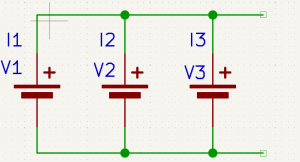
How Parallel Batteries Work
This arrangement is useful when:
- ⏱️ Longer operating time is required
- ⚡ Higher current delivery is needed
- 🔌 Same voltage must be maintained
Important: Parallel sources must be well matched, as differences in voltage can cause unwanted circulating currents!
The Formula
Where:
- I_total = Combined current capacity
- I1, I2, I3 = Individual battery current ratings
Voltage behavior: The effective voltage is the least of all connected voltages.
| Configuration | Voltage | Current |
|---|---|---|
| Single battery (2000mAh) | 3.7V | 2000mAh |
| Three batteries in parallel | 3.7V | 6000mAh total |
When connecting batteries in parallel:
- ✅ Use batteries with same voltage rating
- ✅ Use batteries with same chemistry
- ✅ Use batteries with similar age/condition
- ❌ Mixing different voltages causes dangerous current circulation
🔋 Series-Parallel Battery Combinations
To increase both voltage and current:
- Add batteries in series → increases voltage
- Add batteries in parallel → increases current
Example: 3S2P battery pack
- 3S = 3 cells in series (3 × 3.7V = 11.1V)
- 2P = 2 cells in parallel (doubles current capacity)

This is how lithium battery packs are built from individual cells:

Individual lithium cells - the building blocks
Battery packs built from various combinations based on requirements
| Configuration | Voltage | Capacity | Use Case |
|---|---|---|---|
| 1S1P | 3.7V | 2000mAh | Small sensors |
| 3S1P | 11.1V | 2000mAh | Drones (higher voltage) |
| 3S2P | 11.1V | 4000mAh | Longer flight time |
| 4S3P | 14.8V | 6000mAh | Professional equipment |
🚧 Resistors in Series
Resistors behave differently depending on how they are connected. In a series resistor network, resistances add together, increasing the total resistance.

How Series Resistors Work
As total resistance increases, current decreases for a given voltage (according to Ohm's Law).
Important properties:
- 🌊 Same current flows through each resistor
- ⚡ Voltage divides across them based on resistance values
- 📈 Total resistance increases with each added resistor
The Formula
Where:
- R_total = Total resistance offered
- R1, R2, R3 = Individual resistance values
Voltage Distribution in Series
The current will be the same through all resistors.
The voltages across these resistors will be different.
Let's calculate the voltage across R1:
Given:
- R1 =
10kΩ(10,000 ohms) - Current I =
3mA(0.003 amperes)
Applying Ohm's Law:
V = I × R
V1 = 3mA × 10kΩ
V1 = 0.003A × 10,000Ω
V1 = 30V
Result: The voltage drop across R1 is 30V.
In similar way, the rest of the voltages can be calculated using the same formula!
| Resistor | Resistance | Current | Voltage Drop |
|---|---|---|---|
| R1 | 10kΩ | 3mA | 30V |
| R2 | 5kΩ | 3mA | 15V |
| R3 | 2kΩ | 3mA | 6V |
| Total | 17kΩ | 3mA | 51V |
🚧 Resistors in Parallel
In a parallel resistor network, the total resistance decreases as more resistors are added. This allows more current to flow from the same voltage source.
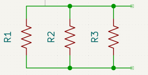
How Parallel Resistors Work
In this configuration:
- ⚡ Voltage is the same across each resistor
- 🌊 Current divides among the branches
- 📉 Total resistance decreases with each added resistor
Real-world use: Parallel configurations are widely used in power distribution systems to ensure consistent voltage delivery to multiple loads.
The Formula
Or rearranged:
Where:
- R_total = Total resistance offered
- R1, R2, R3 = Individual resistance values
Each resistance will draw different currents while all of them have common voltage across them.
The path with less resistance will carry more current!
📊 Quick Reference: Series vs Parallel
| Property | Series | Parallel |
|---|---|---|
| Total Resistance | Increases (R1 + R2 + R3) | Decreases (1/R1 + 1/R2 + 1/R3) |
| Current | Same through all | Divides among branches |
| Voltage | Divides across components | Same across all |
| Use Case | Voltage division | Current distribution |
For Batteries (Voltage Sources)
| Property | Series | Parallel |
|---|---|---|
| Voltage | Adds up (V1 + V2 + V3) | Same (limited by weakest) |
| Current | Limited by weakest | Adds up (I1 + I2 + I3) |
| Use Case | Higher voltage needed | Longer runtime needed |
Understanding series and parallel combinations transforms Ohm's Law from a simple equation into a powerful analytical tool.
It allows engineers to:
- 🎚️ Shape voltage levels for different components
- 🌊 Control current flow through various paths
- 🛡️ Design safe systems that prevent overload
- ⚡ Create efficient circuits with optimal power usage
- 🔧 Build reliable systems that work as intended
This knowledge is the foundation of all circuit design and analysis!