Voltage Divider and Current Divider
Tapping Into Voltage and Distributing Current
Imagine you're filling a water tank on the second floor of a building, but the water pipe runs down the stairs, through the first floor, and comes out at street level. At each stage, there's a valve that creates resistance to the water flow. Now, think about how the water pressure drops as it flows through.
Your battery is like the water tank at the top - it pushes the current through your circuit. But what if you only need a certain voltage at a specific point? This is where voltage dividers come in.
This chapter covers two fundamental circuit techniques:
- Voltage Divider - Getting a lower voltage from a higher voltage source
- Current Divider - Distributing current among parallel paths
These are among the most frequently used circuits in electronics!
⚡ Voltage Divider - Stepping Down Voltage
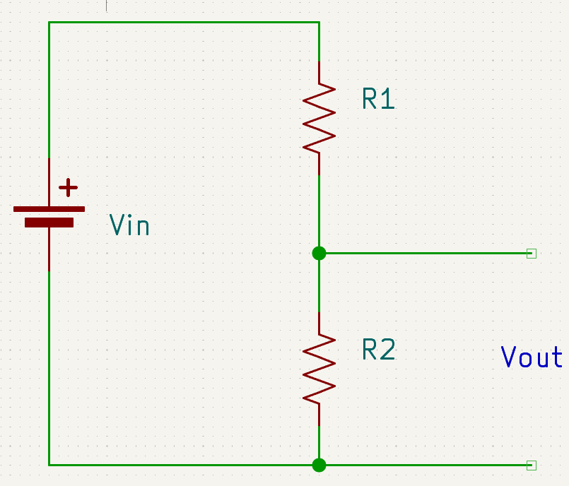
A voltage divider is like tapping into that water pipe at an intermediate point to get a lower pressure than what the main tank provides. In electronics, it's simply two resistors connected in series with your power supply.
How Voltage Dividers Work
The voltage "drops" or gets "used up" by each resistor, and you measure the voltage at the point between them. This is incredibly useful!
Perhaps your sensor only works with 5 volts, but your battery provides 12 volts. A voltage divider lets you convert that 12V down to exactly 5V using just two resistors!
The Voltage Divider Formula
Where:
- V_out = Output voltage (voltage at the divider point)
- V_in = Input voltage (supply voltage)
- R1 = First resistor (top, connected to V_in)
- R2 = Second resistor (bottom, connected to ground)
The formula is actually quite simple once you understand the concept:
The voltage you get at the divider point equals your input voltage multiplied by the ratio of the second resistor to the total resistance.
- If both resistors are equal → you get exactly half your input voltage
- If R2 is smaller → you get less voltage
- If R2 is larger → you get more voltage
It's like adjusting the valve positions to control the pressure at that point!
Practical Examples
| V_in | R1 | R2 | V_out Calculation | V_out |
|---|---|---|---|---|
| 12V | 10kΩ | 10kΩ | 12 × (10/20) = 12 × 0.5 | 6V |
| 12V | 20kΩ | 10kΩ | 12 × (10/30) = 12 × 0.33 | 4V |
| 9V | 6kΩ | 3kΩ | 9 × (3/9) = 9 × 0.33 | 3V |
| 5V | 1kΩ | 1kΩ | 5 × (1/2) = 5 × 0.5 | 2.5V |
Given:
- V_in = 12V
- R1 = 10kΩ
- R2 = 5kΩ
- What is V_out?
Solution:
V_out = V_in × (R2 / (R1 + R2))
V_out = 12V × (5kΩ / (10kΩ + 5kΩ))
V_out = 12V × (5kΩ / 15kΩ)
V_out = 12V × 0.333
V_out = 4V
Result: The output voltage is 4V - exactly one-third of the input!
Common Applications
| Application | Purpose | Example |
|---|---|---|
| Sensor interfacing | Match voltage levels | Convert 5V to 3.3V for microcontroller |
| Reference voltage | Create precise voltage | Generate 2.5V reference from 5V supply |
| Signal conditioning | Adjust signal levels | Scale down analog signals |
| Battery monitoring | Read battery voltage | Measure 12V battery with 5V ADC |
| Biasing circuits | Set operating points | Bias transistor base |
Voltage dividers have limitations:
- ⚠️ Load dependent - Output voltage changes when you draw current
- ⚠️ Power waste - Current flows continuously through both resistors
- ⚠️ Not regulated - Output voltage varies with input voltage
- ⚠️ Low current only - Use voltage regulators for higher current needs
Use voltage dividers for:
- ✅ Light loads (sensors, reference inputs)
- ✅ Signal conditioning
- ✅ Voltage sensing
Don't use for:
- ❌ Powering motors or LEDs
- ❌ High current applications
- ❌ When precise regulation is needed
🌊 Current Divider - Splitting Current Flow
Now, current dividers work the opposite way. When you have parallel paths for current to flow, the current doesn't split equally - it splits based on resistance.
The path with less resistance gets more of the current.
It's like having two water pipes of different widths:
- The wider pipe (less resistance) carries more water flow
- The narrower pipe (more resistance) carries less water flow
This matters a lot in real circuits because if you're connecting components in parallel, they need to share the current appropriately, or one path might burn up from too much current!
How Current Dividers Work
In parallel circuits:
- Voltage is the same across all branches
- Current divides inversely proportional to resistance
- Lower resistance = Higher current
- Higher resistance = Lower current
The Current Divider Formula
For two resistors in parallel:
Where:
- I_total = Total current entering the parallel combination
- I1 = Current through R1
- I2 = Current through R2
- R1, R2 = Parallel resistor values
Notice how the formula is "opposite" to voltage divider:
- Current through R1 depends on R2 in the numerator
- Current through R2 depends on R1 in the numerator
Why? Current prefers the path of least resistance, so the current through one resistor is inversely proportional to its resistance!
Practical Examples
| I_total | R1 | R2 | I1 Calculation | I1 | I2 |
|---|---|---|---|---|---|
| 6A | 10Ω | 10Ω | 6 × (10/20) | 3A | 3A |
| 6A | 20Ω | 10Ω | 6 × (10/30) | 2A | 4A |
| 9A | 6Ω | 3Ω | 9 × (3/9) | 3A | 6A |
| 10A | 5Ω | 5Ω | 10 × (5/10) | 5A | 5A |
Given:
- I_total = 10A
- R1 = 20Ω
- R2 = 10Ω
- What are I1 and I2?
Solution:
I1 = I_total × (R2 / (R1 + R2))
I1 = 10A × (10Ω / (20Ω + 10Ω))
I1 = 10A × (10Ω / 30Ω)
I1 = 10A × 0.333
I1 = 3.33A

I2 = I_total × (R1 / (R1 + R2))
I2 = 10A × (20Ω / 30Ω)
I2 = 10A × 0.667
I2 = 6.67A
Check: I1 + I2 = 3.33A + 6.67A = 10A ✓
Result: The smaller resistor (10Ω) carries twice the current of the larger resistor (20Ω)!
Common Applications
| Application | Purpose | Example |
|---|---|---|
| LED circuits | Balance brightness | Multiple parallel LEDs |
| Current sensing | Shunt resistors | Measure current with low resistance |
| Load balancing | Distribute power | Parallel power resistors |
| Protection circuits | Bypass excess current | Parallel fuses or diodes |
📊 Quick Reference: Voltage vs Current Divider
| Property | Voltage Divider | Current Divider |
|---|---|---|
| Configuration | Series resistors | Parallel resistors |
| What divides | Voltage | Current |
| What stays same | Current through all | Voltage across all |
| Formula pattern | Direct proportion | Inverse proportion |
| Output depends on | Resistor ratio | Resistor ratio (inverse) |
| Common use | Reduce voltage | Distribute current |
Key Differences
Voltage Divider:
- Series connection
- Larger resistor gets more voltage drop
- V_out uses R2 in numerator (direct)
Current Divider:
- Parallel connection
- Smaller resistor gets more current
- I1 uses R2 in numerator (inverse)
Remember: Voltage divides directly, current divides inversely!
🔧 Design Tips and Best Practices
For Voltage Dividers
-
Choose resistor values:
- Higher values (10kΩ - 100kΩ) = less power waste
- Lower values (1kΩ - 10kΩ) = better stability with loads
-
Calculate power dissipation:
P = V² / R_total -
Consider load effect:
- Output voltage drops when current is drawn
- Use buffer amplifier for heavy loads
-
Standard resistor selection:
- Use E12 or E24 series values
- 10kΩ, 4.7kΩ, 2.2kΩ, 1kΩ are common
For Current Dividers
-
Ensure adequate power rating:
- Calculate:
P = I² × Rfor each resistor - Use resistors rated at least 2x calculated power
- Calculate:
-
Match resistor tolerances:
- Use 1% or better for precision current splitting
- Temperature coefficients matter in high-power applications
-
Consider parallel combinations:
- Use standard values in parallel for odd ratios
- Multiple small resistors can share power dissipation
Voltage dividers and current dividers are fundamental building blocks in electronics.
Voltage Divider:
- 📉 Reduces voltage using series resistors
- 🔧 Essential for sensor interfacing and signal conditioning
- ⚠️ Limited to light loads
Current Divider:
- 🌊 Splits current using parallel resistors
- ⚖️ Current flows inversely to resistance
- 💡 Critical for load balancing and current sensing
Master these concepts - you'll use them constantly in circuit design!