Network Theorems: Thevenin, Norton, Superposition
Shortcuts for Simplifying Complex Circuits
These theorems are powerful shortcuts that simplify complex circuits. Instead of solving everything with KVL and KCL, these methods let you focus on what you need.
Complex circuits can be simplified!
Instead of analyzing every component, these theorems let you:
- Replace complex networks with simple equivalent circuits
- Focus on specific parts of a circuit
- Analyze one element at a time
- Save time and reduce errors
⚡ Thevenin's Theorem
The Theorem
"Any linear circuit with voltage sources and resistors can be replaced by a single voltage source (Thevenin voltage) in series with a single resistor (Thevenin resistance)."
No matter how complex the circuit, from the perspective of two terminals, it can be simplified to just:
- One voltage source
- One resistor in series
Why Use Thevenin's Theorem?
Perfect for:
- 🎯 Finding voltage/current in one specific branch without analyzing the whole circuit
- 🔌 Simplifying sensor circuits for easier design
- 🔋 Modeling power sources accurately
- 🛠️ Load analysis - testing different loads without recalculating everything
- 📊 Design optimization - quick what-if scenarios
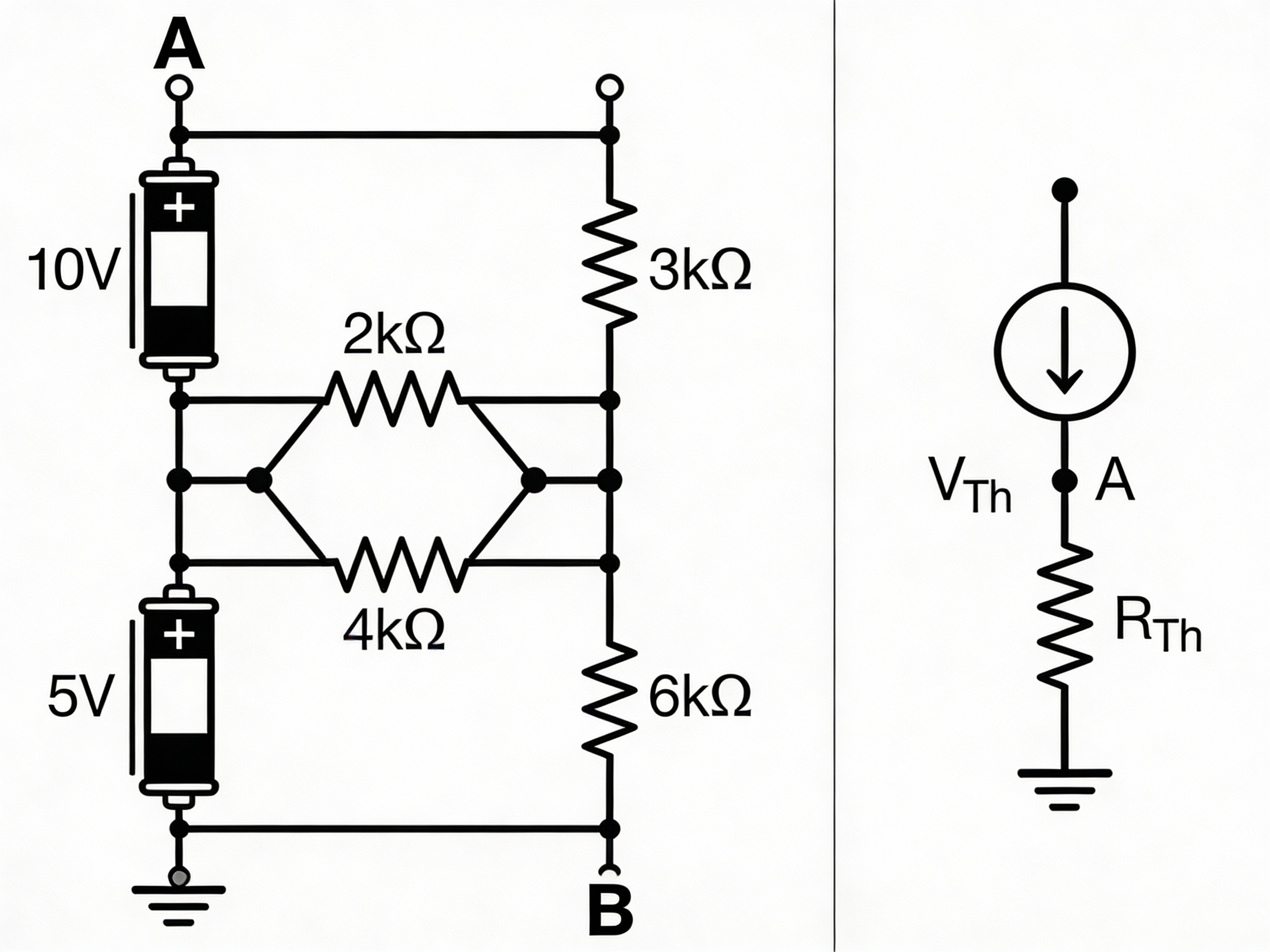
Thevenin's Theorem - Step by Step
- Identify the load (the part you care about)
- Remove the load (disconnect it from the circuit)
- Find Thevenin voltage (V_th) = Open circuit voltage across the load terminals
- Find Thevenin resistance (R_th) = Resistance looking back into the circuit with all sources turned off:
- Voltage sources → Replace with short circuit (wire)
- Current sources → Replace with open circuit (remove)
- Redraw as simple circuit: V_th in series with R_th, then reconnect the load
Practical Example
Original circuit:
- 12V battery
- R1 = 10Ω in series with battery
- R2 = 20Ω to ground
- Load resistor R_L connected between R1-R2 junction and ground
Find Thevenin equivalent:
Step 1: Remove R_L
Step 2: Find V_th (open circuit voltage):
Using voltage divider:
V_th = 12V × (20Ω / (10Ω + 20Ω))
V_th = 12V × (20/30)
V_th = 8V
Step 3: Find R_th (short the battery, find resistance):
R_th = R1 || R2
R_th = (10Ω × 20Ω) / (10Ω + 20Ω)
R_th = 200/30
R_th = 6.67Ω
Step 4: Thevenin equivalent = 8V source with 6.67Ω in series
Now you can easily analyze different loads by just connecting them to this simple equivalent!
🔄 Norton's Theorem
The Theorem
"Any linear circuit can be replaced by a single current source (Norton current) in parallel with a single resistor (Norton resistance)."
This is the dual of Thevenin's theorem:
- Thevenin = Voltage source + Series resistor
- Norton = Current source + Parallel resistor
Converting Between Thevenin and Norton
The two are equivalent!
Where:
- V_th = Thevenin voltage
- I_N = Norton current
- R_th = Thevenin resistance
- R_N = Norton resistance (same value!)
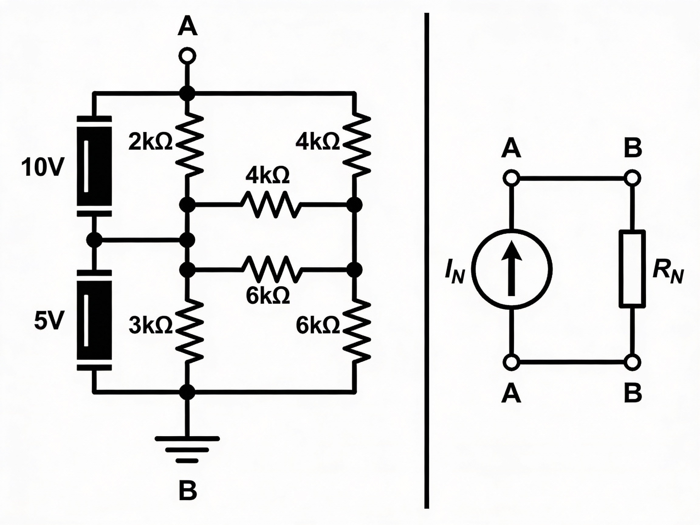
Norton's Theorem - Step by Step
- Identify the load (the part you care about)
- Remove the load
- Find Norton current (I_N) = Short circuit current through the load terminals
- Find Norton resistance (R_N) = Same as Thevenin resistance (resistance with sources off)
- Redraw as: I_N current source in parallel with R_N, then reconnect the load
📊 Thevenin vs Norton Comparison
| Property | Thevenin | Norton |
|---|---|---|
| Source type | Voltage source | Current source |
| Resistor connection | Series | Parallel |
| Easy to find when | Voltage calculations simpler | Current calculations simpler |
| Better for | Voltage-based analysis | Current-based analysis |
| Resistance | R_th | R_N (same value!) |
| Relationship | V_th = I_N × R | I_N = V_th / R |
Both methods give identical results!
Choose whichever is easier to calculate for your specific circuit.
- Lots of voltage sources? → Use Thevenin
- Lots of current sources? → Use Norton
- Need both? → Convert between them easily!
🔀 Superposition Theorem
The Theorem
"In a linear circuit with multiple sources, the total response (voltage or current) is the sum of responses from each source acting alone."
Method:
- Analyze the circuit with one source at a time
- Turn off all other sources
- Add up all the individual responses
How to "Turn Off" Sources
When deactivating sources:
Voltage sources:
- Replace with short circuit (0Ω wire)
- Voltage = 0V
Current sources:
- Replace with open circuit (remove it)
- Current = 0A
Keep all resistors in the circuit!
Superposition - Step by Step
- Choose one source to analyze
- Turn off all other sources (short voltage sources, open current sources)
- Calculate the response (current or voltage) from this one source
- Repeat for each source
- Add all responses algebraically (watch the signs!)
Practical Example
Circuit with two voltage sources:
- V1 = 12V with R1 = 6Ω
- V2 = 6V with R2 = 3Ω
- R_load = 2Ω connected between them
Find current through R_load:
Step 1 - Analyze V1 alone (short V2):
Total resistance = R1 + (R2 || R_load)
Calculate I1 through R_load
Step 2 - Analyze V2 alone (short V1):
Total resistance = R2 + (R1 || R_load)
Calculate I2 through R_load
Step 3 - Add results:
I_total = I1 + I2
(Watch direction - one may be negative!)
💡 When to Use Each Theorem
| Situation | Best Theorem | Why |
|---|---|---|
| Analyzing one load with many sources | Thevenin/Norton | Simplify everything to one source |
| Testing different loads | Thevenin/Norton | Calculate equivalent once, try many loads |
| Multiple independent sources | Superposition | Analyze each source separately |
| Mix of AC and DC sources | Superposition | Separate DC and AC analysis |
| Understanding source contributions | Superposition | See how each source affects the circuit |
| Quick calculation needed | Thevenin | Usually fastest |
🔧 Real-World Applications
Thevenin's Theorem:
- 📱 Battery modeling for IoT devices
- 🔌 Power supply design
- 📡 Sensor interface circuits
- 🛰️ Signal source modeling
Norton's Theorem:
- ⚡ Current source analysis
- 🔋 Solar panel modeling
- 💡 LED driver design
- 🎚️ Current distribution networks
Superposition:
- 🌞 Solar + battery systems (multiple sources)
- 🔊 Audio circuits with multiple inputs
- 📡 RF circuits with multiple signals
- 🏭 Power distribution with multiple generators
📊 Quick Reference Summary
Thevenin Equivalent
Find: V_th (open circuit voltage)
Find: R_th (resistance with sources off)
Result: V_th in series with R_th
Norton Equivalent
Find: I_N (short circuit current)
Find: R_N (resistance with sources off)
Result: I_N in parallel with R_N
Superposition
For each source:
  - Turn off other sources
  - Calculate response
Sum all responses
🎯 Practical Tips
Thevenin/Norton:
- ✅ Always remove the load first before finding equivalent
- ✅ Double-check source deactivation (short voltage, open current)
- ✅ Verify units (V_th in volts, R_th in ohms)
- ✅ Test with simple values to verify your equivalent works
Superposition:
- ✅ Draw separate circuits for each source analysis
- ✅ Label current directions clearly
- ✅ Watch the signs when adding (currents may oppose)
- ✅ Verify final answer makes physical sense
Common Mistakes
❌ Forgetting to remove the load in Thevenin/Norton
❌ Not turning off sources correctly (voltage ≠ open, current ≠ short)
❌ Wrong signs in superposition addition
❌ Applying to non-linear circuits (these only work with linear circuits!)
✅ Always verify by checking with KVL/KCL on the final result
🚀 Why These Simplify Real IoT Circuits
Modern circuits are complex:
- Multiple power sources (solar, battery, USB)
- Many loads (sensors, microcontrollers, radios)
- Interconnected networks
These theorems let you:
- 🎯 Focus on one part at a time
- 🔄 Swap components easily
- 📊 Optimize designs faster
- 🛠️ Troubleshoot systematically
- 💰 Save time in development
Without these theorems, analyzing every component interaction would be impractical!
Network theorems are powerful circuit simplification tools:
Thevenin's Theorem:
- Replace complex circuit with: Voltage source + Series resistor
- Best for: Load analysis, power source modeling
- Steps: Remove load → Find V_th and R_th → Redraw
Norton's Theorem:
- Replace complex circuit with: Current source + Parallel resistor
- Dual of Thevenin (easily convertible)
- Best for: Current source circuits
Superposition Theorem:
- Analyze one source at a time, then add results
- Turn off sources: Voltage → short, Current → open
- Best for: Multiple independent sources
All three:
- ✅ Work only with linear circuits
- ✅ Simplify complex analysis dramatically
- ✅ Essential for real-world circuit design
- ✅ Form the foundation of modern circuit simulation tools
Master these - they'll save you countless hours in circuit analysis and design!