Phase Angle and Phasor Diagrams – Visualizing AC Relationships
In AC circuits, resistance and reactance do not add like ordinary numbers because they are out of phase.
To understand this visually, we use phasor diagrams.
Phasor diagrams turn time-based sine waves into static vectors, making AC analysis much simpler.
What Is a Phasor?
A phasor is a rotating vector that represents a sinusoidal voltage or current.
- Length of the arrow → magnitude (voltage or current)
- Angle of the arrow → phase relative to a reference
Think of a clock hand:
- Length = how strong the signal is
- Angle = where the signal is in its cycle

Phase Angle
The phase angle is the time difference between voltage and current, expressed as an angle.
Measured in:
- Degrees (0°–360°)
- Radians (0–2π)
Phase Relationships
Different components create different phase shifts.
| Circuit Type | Phase Relationship |
|---|---|
| Pure resistive | Voltage and current in phase (0°) |
| Pure inductive | Current lags voltage by 90° |
| Pure capacitive | Current leads voltage by 90° |

Why Phase Angle Matters
Phase angle determines how efficiently a circuit uses power.
It affects:
- Power factor
- Reactive power (stored energy)
- Real power (useful work)
- Resonance conditions
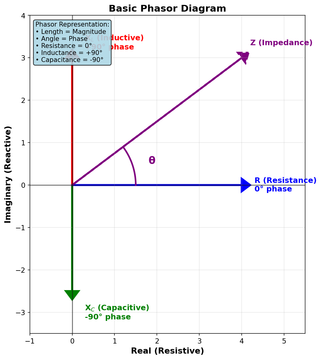
Phasor Diagram Construction
To draw a phasor diagram:
- Draw a horizontal reference line (usually resistance)
- Draw reactance at ±90°:
- Upward for inductive
- Downward for capacitive
- Draw the diagonal vector combining both
- The angle between impedance and resistance is the phase angle

Example: RL Circuit
Given:
- Resistance = 100 Ω
- Inductive reactance = 80 Ω
Phasors:
- R → horizontal (0°)
- XL → vertical up (90°)
- Z → diagonal
Phase angle:
A 39° phase angle means current lags voltage by 39°.

Real-World Impact
Poor phase angle means wasted power.
In power systems:
- Large phase angles cause low power factor
- Utilities charge penalties for excessive reactive power
- Capacitor banks are used to correct phase angle

Why Phasors Are Powerful
Phasors convert trigonometry into simple geometry.
- Time-domain sine waves → vectors
- Differential equations → algebra
- Complex AC behavior → right triangles
Key Takeaway
Phasor diagrams are the bridge between intuition and calculation.
They make phase angle, impedance, and power relationships visible — and without them, AC circuit analysis would be nearly impossible.