Counters: Asynchronous and Synchronous
Introduction
Imagine you're at a turnstile counting people entering a stadium, or a digital clock ticking away seconds, or a CPU keeping track of instruction cycles. All these scenarios need counters—sequential circuits that go through a defined sequence of states with each clock pulse.
Counters are everywhere in digital systems:
- Timers and clocks
- Frequency dividers
- Address generators for memory
- Event counters
- Digital frequency meters
- Sequence generators
Counters are among the most widely used sequential circuits. Understanding them gives you the foundation for building more complex systems like state machines, timers, and control units. Every digital clock you've ever seen is built around counters!
Counter Fundamentals
What is a Counter?
A counter is a sequential circuit that progresses through a predetermined sequence of states upon receiving input clock pulses.
Basic Properties:
- Built from flip-flops (usually T or JK)
- Has a defined sequence (usually binary)
- Advances on clock edges
- Can count up or down
- May have additional control inputs (reset, load, enable)
Counter Classification:
Counters
├── By Direction
│   ├── Up Counters (0→1→2→3...)
│   ├── Down Counters (3→2→1→0...)
│   └── Up-Down Counters (bidirectional)
├── By Clocking
│   ├── Asynchronous (Ripple)
│   └── Synchronous
└── By Sequence
    ├── Binary (follows binary sequence)
    └── Non-Binary (arbitrary sequence)
Modulus of a Counter
The modulus (MOD) is the number of states in the counter's sequence.
| Counter Type | Modulus | States | Bits Required |
|---|---|---|---|
| MOD-2 | 2 | 0, 1 | 1 |
| MOD-4 | 4 | 0, 1, 2, 3 | 2 |
| MOD-8 | 8 | 0-7 | 3 |
| MOD-10 | 10 | 0-9 | 4 |
| MOD-16 | 16 | 0-15 | 4 |
| MOD-N | N | 0 to N-1 | ⌈log₂N⌉ |
Relationship:
Example: MOD-10 counter needs ⌈log₂10⌉ = ⌈3.32⌉ = 4 flip-flops
Asynchronous Counters (Ripple Counters)
3-Bit Asynchronous Binary Counter
The simplest counter: uses two T flip-flops.
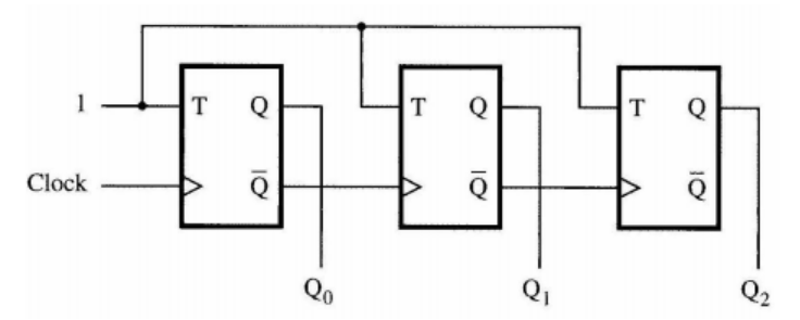
Operation:
- FF0 toggles on every external clock rising edge
- FF1 toggles on every FF0 falling edge (Q0: 1→0 transition)
- Creates divide-by-2 then divide-by-2 again = divide-by-4 overall

State Sequence:
| CLK Pulse | Q2 Q1 Q0 | Decimal |
|---|---|---|
| 0 | 0 0 0 | 0 |
| 1 | 0 0 1 | 1 |
| 2 | 0 1 0 | 2 |
| 3 | 0 1 1 | 3 |
| 4 | 1 0 0 | 4 |
| 5 | 1 0 1 | 5 |
| 6 | 1 1 0 | 6 |
| 7 | 1 1 1 | 7 |
| 8 | 0 0 0 | 0 (wraps around) |
Called "ripple" counter because the clock "ripples" through the flip-flops like a wave—each FF clocks the next one. This creates propagation delay accumulation.
4-Bit Asynchronous Binary Counter (MOD-16)
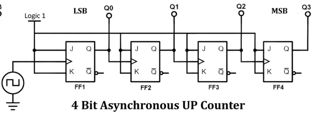
Characteristics:
- Modulus: 16 (counts 0-15)
- States: 0000 to 1111 in binary
- Frequency division: Output frequency = Input frequency / 16
- Q0 changes at CLK rate (LSB)
- Q3 changes at CLK/8 rate (MSB)
State Sequence (partial):
| CLK | Q3 | Q2 | Q1 | Q0 | Decimal |
|---|---|---|---|---|---|
| 0 | 0 | 0 | 0 | 0 | 0 |
| 1 | 0 | 0 | 0 | 1 | 1 |
| 2 | 0 | 0 | 1 | 0 | 2 |
| 3 | 0 | 0 | 1 | 1 | 3 |
| 4 | 0 | 1 | 0 | 0 | 4 |
| ... | ... | ... | ... | ... | ... |
| 15 | 1 | 1 | 1 | 1 | 15 |
| 16 | 0 | 0 | 0 | 0 | 0 |
Propagation Delay in Ripple Counters
Major Limitation: Accumulated delay through cascaded flip-flops.
Total Propagation Delay:
Where:
- n = number of flip-flops
- t_pd(FF) = propagation delay of one flip-flop
Example:
- 4-bit counter
- Each FF has t_pd = 10ns
- Total delay = 4 × 10ns = 40ns
Problem: At high frequencies, next clock pulse may arrive before all FFs have settled—causing errors!
Maximum Frequency:
For 4-bit counter with 10ns FF delay:

Asynchronous counters are slow because of cumulative delay. For high-speed applications (>50MHz), use synchronous counters instead!
MOD-N Asynchronous Counter
To create a counter with modulus other than 2^n, add reset logic.
MOD-10 Counter (Decade Counter) Example:
Goal: Count 0-9, then reset to 0
Approach:
- Start with 4-bit counter (can count 0-15)
- Detect when count reaches 10 (1010 in binary)
- Asynchronously clear all flip-flops
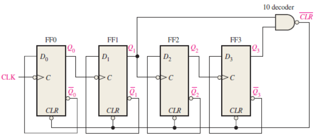
Detection Logic:
- Decimal 10 = 1010 binary = Q3=1, Q2=0, Q1=1, Q0=0
- Use NAND gate: Q3 · Q1 = 1 only when count = 10, 11, 14, or 15
- Counter resets before reaching 11, so only 10 triggers reset
State Sequence:
| CLK | Q3 Q2 Q1 Q0 | Decimal | Notes |
|---|---|---|---|
| 0-9 | 0000-1001 | 0-9 | Normal counting |
| 10 | 1010 | 10 | Briefly appears then resets |
| 10+ | 0000 | 0 | Reset to 0 |
The counter briefly enters state 10 before resetting. This ~10ns glitch can cause problems in some applications. Solution: Use synchronous counter or add output register.
Asynchronous Down Counter
To count down instead of up, clock each FF from the Q̄ output of the previous FF.
Circuit Modification:
FF0 Q̄ → FF1 CLK
FF1 Q̄ → FF2 CLK
etc.
State Sequence: 15→14→13→...→1→0→15...
Synchronous Counters
Key Difference
In synchronous counters, all flip-flops are clocked simultaneously by the same clock signal. This eliminates propagation delay accumulation!
Advantages:
- ✅ Much faster (no accumulated delays)
- ✅ No glitches between states
- ✅ Easier timing analysis
- ✅ Better for high-speed designs
Disadvantage:
- ❌ More complex logic required (but worth it!)
2-Bit Synchronous Binary Counter
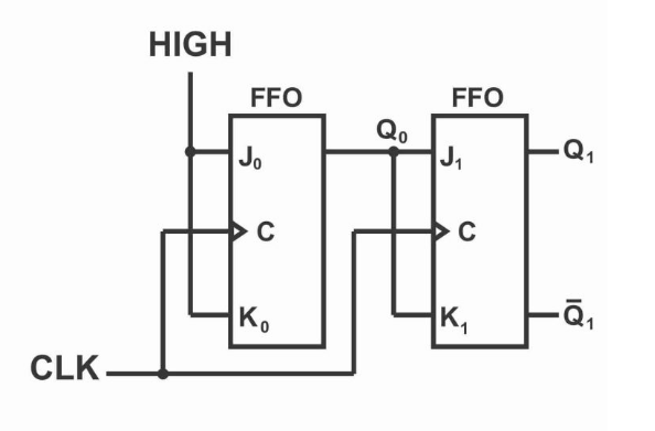
Operation Logic:
- LSB (Q0) toggles every clock cycle
- MSB (Q1) toggles only when Q0=1
Truth Table for Next State:
| Current (Q1 Q0) | Next (Q1 Q0) | J0 K0 | J1 K1 |
|---|---|---|---|
| 0 0 | 0 1 | 1 1 | 0 0 |
| 0 1 | 1 0 | 1 1 | 1 1 |
| 1 0 | 1 1 | 1 1 | 0 0 |
| 1 1 | 0 0 | 1 1 | 1 1 |
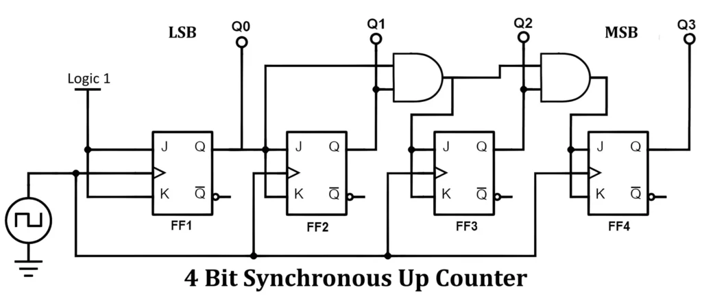
4-Bit Synchronous Binary Counter
Design Rules for Binary Up Counter:
- Each FF toggles when all lower FFs are 1
- FF_n toggles when Q_(n-1) · Q_(n-2) · ... · Q_0 = 1
Propagation Delay:
- Only one flip-flop delay regardless of counter size!
- Maximum frequency much higher than ripple counter
Example Timing:
- Ripple counter: 40ns total delay (10ns × 4 FFs)
- Synchronous counter: 10ns total delay (one FF only)
- Synchronous is 4× faster for 4-bit counter!
In modern digital design (FPGAs, microcontrollers), synchronous counters are the norm. Asynchronous counters are mainly for learning or very specific low-speed applications.
Synchronous MOD-N Counters
To create MOD-N synchronous counter:
- Use sufficient flip-flops: ⌈log₂N⌉
- Add logic to reset or skip states after (N-1)
MOD-10 Synchronous Counter:
Approach 1: Synchronous Clear
- Detect count = 9
- On next clock, load 0 into all FFs
Approach 2: Synchronous Load
- Use counter with parallel load
- When count = 9, load 0 on next clock
Up-Down Counter
Up-Down counter can count in either direction based on control signal.
Design Approach:
- Add multiplexers to select increment or decrement logic
- UP signal selects which logic path is active
Applications:
- Position tracking (encoder systems)
- Reversible timers
- Bidirectional event counting
Commercial ICs:
- 74HC191: Synchronous up/down counter
- 74HC193: Synchronous 4-bit binary up/down counter
Presettable Counters
Presettable counters can be loaded with an initial value.
Inputs:
- LOAD: Control signal to load data
- D3 D2 D1 D0: Parallel data inputs
- CLK: Clock signal
Operation:
- When LOAD=1: On next clock, load D inputs into counter
- When LOAD=0: Normal counting
Applications:
- Starting count from specific value
- Implementing countdown timers
- Creating custom sequences

Counter Applications
1. Frequency Divider
Most Common Application: Divide input frequency by power of 2.
Circuit:
- N-bit counter
- Output Q_(N-1) has frequency = f_input / 2^N
Example:
- 4-bit counter
- Input: 16 MHz
- Q0 output: 8 MHz (÷2)
- Q1 output: 4 MHz (÷4)
- Q2 output: 2 MHz (÷8)
- Q3 output: 1 MHz (÷16)
2. Digital Clock
Design: Cascade multiple counters
1 Hz input → MOD-60 counter (seconds) →
             MOD-60 counter (minutes) →
             MOD-24 counter (hours)

3. Event Counter
Count external events (button presses, sensor triggers, etc.)
Circuit:
- Counter
- Input: Event signal
- Output: Number of events counted
- Display: 7-segment or LCD
4. Sequence Generator
Generate specific sequences for control logic.
Example: Traffic Light Controller
State 0: Green (30 sec)
State 1: Yellow (5 sec)
State 2: Red (30 sec)
Use counter + decoder to generate states.
5. PWM Generation
Use counter + comparator to generate PWM signals.
Ring Counters and Johnson Counters
Ring Counter
Ring counter: Shift register with output fed back to input.

4-Bit Ring Counter States:
| CLK | Q3 | Q2 | Q1 | Q0 |
|---|---|---|---|---|
| 0 | 0 | 0 | 0 | 1 |
| 1 | 0 | 0 | 1 | 0 |
| 2 | 0 | 1 | 0 | 0 |
| 3 | 1 | 0 | 0 | 0 |
| 4 | 0 | 0 | 0 | 1 |
Characteristics:
- Modulus: N (same as number of flip-flops)
- Advantage: One-hot outputs (only one HIGH at a time)
- Disadvantage: Inefficient (needs N FFs for MOD-N)
Applications:
- State machines where one-hot encoding simplifies logic
- Stepper motor control
- Sequential control circuits
Johnson Counter (Twisted Ring Counter)
Johnson counter: Ring counter with inverted feedback.
4-Bit Johnson Counter States:
| CLK | Q3 | Q2 | Q1 | Q0 | Decimal |
|---|---|---|---|---|---|
| 0 | 0 | 0 | 0 | 0 | 0 |
| 1 | 0 | 0 | 0 | 1 | 1 |
| 2 | 0 | 0 | 1 | 1 | 3 |
| 3 | 0 | 1 | 1 | 1 | 7 |
| 4 | 1 | 1 | 1 | 1 | 15 |
| 5 | 1 | 1 | 1 | 0 | 14 |
| 6 | 1 | 1 | 0 | 0 | 12 |
| 7 | 1 | 0 | 0 | 0 | 8 |
| 8 | 0 | 0 | 0 | 0 | 0 |
Characteristics:
- Modulus: 2N (twice the number of flip-flops!)
- More efficient than ring counter
- Self-starting (can recover from invalid states)
Applications:
- Frequency dividers
- Sequence generators
- Switch debouncing
Counter ICs (Integrated Circuits)
Popular Counter ICs
| IC Number | Type | Description |
|---|---|---|
| 74HC161 | Sync | 4-bit binary, synchronous, presettable |
| 74HC163 | Sync | 4-bit binary, synchronous, no async clear |
| 74HC190 | Sync | BCD up/down counter |
| 74HC191 | Sync | Binary up/down counter |
| 74HC193 | Sync | 4-bit binary up/down counter |
| 74HC390 | Async | Dual decade counter |
| 74HC393 | Async | Dual 4-bit binary counter |
| CD4017 | Decade | Johnson counter with 10 decoded outputs |
74HC161 Synchronous Counter
Pinout and Features:
- 4-bit binary counter (0-15)
- Synchronous parallel load
- Synchronous clear
- Ripple carry output (for cascading)
- Clock enable input
Applications:
- Frequency division
- Address generation
- Timing and sequencing
Troubleshooting Counters
Common Problems
1. Counter Stuck at One State
- Check clock signal
- Verify power supply
- Test clear/reset inputs
- Check for damaged IC
2. Counter Skipping States
- Clock signal noise or bouncing
- Timing violations (setup/hold)
- Loose connections
- Decoupling capacitor missing
3. Irregular Counting
- Noisy power supply
- Improper grounding
- Clock frequency too high
- Damaged flip-flop
Debugging Techniques
Tools:
- Logic analyzer (best for viewing all signals simultaneously)
- Oscilloscope (for timing analysis)
- LED indicators (for slow counters)
- Multimeter (DC voltage checks)
Procedure:
- Verify power supply (5V for TTL/CMOS)
- Check clock signal (clean edges, correct frequency)
- Test reset/clear functionality
- Verify output states in sequence
- Check for noise or glitches
Summary
Counters are essential sequential circuits that count clock pulses or events:
✅ Asynchronous (Ripple): Simple but slow due to accumulated delay
✅ Synchronous: Fast, no accumulated delay, industry standard
✅ MOD-N: Can count in any modulus with additional logic
✅ Up-Down: Can count in both directions
✅ Special: Ring and Johnson counters for specific applications
Key Takeaways:
- Asynchronous: Easy to build, but speed-limited by ripple delay
- Synchronous: Preferred for modern designs, much faster
- Modulus: Determines the counting sequence length
- Applications: Frequency division, timing, sequencing, counting
- ICs: Ready-made counter ICs save design time
With counters mastered, we're ready to tackle shift registers—circuits that move data serially or in parallel. Shift registers are crucial for data conversion, storage, and communication!
Further Reading
- "Digital Design" by Morris Mano (Chapter on Counters)
- Datasheet study: 74HC161, 74HC193
- FPGA counter implementations in Verilog/VHDL
- Advanced topics: Gray code counters, Linear Feedback Shift Registers (LFSR)
Practice Problems:
- Design a MOD-12 asynchronous counter
- Calculate max frequency for 8-bit ripple counter (tpd = 8ns per FF)
- Design a synchronous MOD-6 counter using JK flip-flops
- How many flip-flops needed for MOD-100 counter?
- Design a frequency divider: 10 MHz → 1 MHz
- Draw timing diagram for 3-bit Johnson counter
- Interface 74HC161 to create MOD-100 counter (cascade two ICs)