Combinational Circuits: Multiplexers, Decoders, and Encoders
Introduction
Now that we understand Boolean algebra and basic gates, it's time to build something useful! Combinational circuits are digital circuits where the output depends only on the current inputs—there's no memory, no feedback, just pure logic.
Think of combinational circuits as digital "functions":
- Inputs go in
- Logic processes them
- Outputs come out immediately
No history, no state, no memory of what happened before.
A combinational circuit is like a vending machine's selection logic:
- You press buttons (inputs)
- It decides what to dispense (output)
- It doesn't remember what you bought yesterday
That's different from sequential circuits (coming later) which are like a thermostat that remembers the temperature history.
Characteristics of Combinational Circuits
Key Properties:
| Property | Description |
|---|---|
| No Memory | Output depends only on current inputs |
| No Feedback | Outputs don't feed back to inputs |
| Instantaneous | Output changes as soon as input changes (plus propagation delay) |
| Deterministic | Same inputs always produce same output |
Design Process:
- Define the problem and create truth table
- Derive Boolean expressions (SOP or POS)
- Simplify using Boolean algebra or Karnaugh maps
- Implement using logic gates
- Verify functionality
While we say output is "instantaneous," in reality there's propagation delay through each gate (typically nanoseconds). The total delay is the sum of delays through the longest path.
Multiplexers (MUX): Digital Selector Switches
What is a Multiplexer?
A multiplexer (MUX) is a digital switch that selects one of several input signals and forwards it to a single output line.
Think of it as:
- A railroad switch selecting which track to follow
- A TV remote selecting which channel to watch
- A network router deciding which path to send data
Structure:
- N data inputs (I0, I1, I2, ... In-1)
- M select lines (S0, S1, ... Sm-1) where M = log₂(N)
- 1 output (Y)
- Often has an enable input (E)
Key Relationship:
Number of select lines = log₂(number of inputs)
| Data Inputs | Select Lines Needed |
|---|---|
| 2 | 1 |
| 4 | 2 |
| 8 | 3 |
| 16 | 4 |
2:1 Multiplexer (2-to-1 MUX)
Simplest MUX: Two inputs, one select line.

Truth Table:
| S | Y |
|---|---|
| 0 | I0 |
| 1 | I1 |
Boolean Expression:
Interpretation:
- When S=0: Y copies I0
- When S=1: Y copies I1
Real-World Example:
// Software equivalent
int mux_2to1(int I0, int I1, int S) {
    if (S == 0)
        return I0;
    else
        return I1;
}
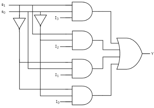
4:1 Multiplexer (4-to-1 MUX)
More Complex: Four inputs, two select lines.

Truth Table:
| S1 | S0 | Y |
|---|---|---|
| 0 | 0 | I0 |
| 0 | 1 | I1 |
| 1 | 0 | I2 |
| 1 | 1 | I3 |
Boolean Expression:
Amazing fact: A multiplexer can implement ANY Boolean function! Connect the select lines to your input variables and set the data inputs to appropriate 0s and 1s. This makes MUX very powerful for prototyping.
Practical Applications of Multiplexers
1. Data Routing
Multiple sensors → MUX → Single ADC (Analog-to-Digital Converter)
Saves cost by sharing one ADC among multiple sensors
2. Communication Systems
- Time-division multiplexing (TDM)
- Combining multiple signals onto one transmission line
3. Digital Systems
- Implementing Boolean functions
- Address decoding
- Data bus selection in CPUs
4. Frequency Division
- Clock signal selection
- Prescaler circuits
Commercial ICs:
- 74HC157: Quad 2:1 MUX
- 74HC153: Dual 4:1 MUX
- 74HC151: 8:1 MUX
- CD4051: 8-channel analog MUX
Demultiplexers (DEMUX): Reverse of Multiplexer
What is a Demultiplexer?
A demultiplexer does the opposite of a MUX: it takes one input and routes it to one of several outputs based on select lines.
Structure:
- 1 data input (I)
- M select lines (S0, S1, ... Sm-1)
- N outputs (Y0, Y1, ... Yn-1) where N = 2^M
- Often has an enable input (E)
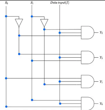
1:4 Demultiplexer

Circuit Implementation:
Truth Table:
| S1 | S0 | Y0 | Y1 | Y2 | Y3 |
|---|---|---|---|---|---|
| 0 | 0 | I | 0 | 0 | 0 |
| 0 | 1 | 0 | I | 0 | 0 |
| 1 | 0 | 0 | 0 | I | 0 |
| 1 | 1 | 0 | 0 | 0 | I |
Boolean Expressions:
Applications:
- Distributing one signal to multiple destinations
- Address decoding in memory systems
- LED matrix control
- Serial-to-parallel data conversion
A demultiplexer is actually a decoder (which we'll learn next) with an enable input that acts as the data input. When enabled, it activates one of the outputs based on the select lines.
Decoders: Binary to One-Hot Conversion
What is a Decoder?
A decoder converts binary information from N input lines to a maximum of 2^N unique output lines. Exactly one output is active (HIGH or LOW depending on design) for each input combination.
Think of it as:
- Binary address → Specific memory location
- Binary code → Which lamp to turn on
- Compressed information → Expanded form
Structure:
- N input lines (address/code)
- 2^N output lines (one active per input combination)
- Often has enable input(s)
2-to-4 Decoder

Truth Table (Active HIGH outputs):
| E | A1 | A0 | Y0 | Y1 | Y2 | Y3 |
|---|---|---|---|---|---|---|
| 0 | X | X | 0 | 0 | 0 | 0 |
| 1 | 0 | 0 | 1 | 0 | 0 | 0 |
| 1 | 0 | 1 | 0 | 1 | 0 | 0 |
| 1 | 1 | 0 | 0 | 0 | 1 | 0 |
| 1 | 1 | 1 | 0 | 0 | 0 | 1 |
Boolean Expressions:

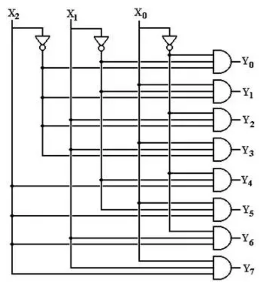
3-to-8 Decoder
Larger Decoder: 3 inputs, 8 outputs
Truth Table:
| E | A2 | A1 | A0 | Active Output |
|---|---|---|---|---|
| 0 | X | X | X | None |
| 1 | 0 | 0 | 0 | Y0 |
| 1 | 0 | 0 | 1 | Y1 |
| 1 | 0 | 1 | 0 | Y2 |
| 1 | 0 | 1 | 1 | Y3 |
| 1 | 1 | 0 | 0 | Y4 |
| 1 | 1 | 0 | 1 | Y5 |
| 1 | 1 | 1 | 0 | Y6 |
| 1 | 1 | 1 | 1 | Y7 |
 |
Practical Decoder Applications
1. Memory Address Decoding
CPU sends address (e.g., 0x00-0x07)
↓
Decoder converts to chip select signals
↓
Activates specific memory chip
2. Seven-Segment Display Decoder
- BCD input (0-9)
- Decoder activates segments to display digit

3. Instruction Decoding in CPUs
- Opcode bits → Decoder → Control signals
4. Demultiplexer Function
- Add data input to decoder's enable = DEMUX!
Commercial ICs:
- 74HC138: 3-to-8 decoder
- 74HC139: Dual 2-to-4 decoder
- 74HC154: 4-to-16 decoder
- 7447/7448: BCD to 7-segment decoder
Encoders: Opposite of Decoders
What is an Encoder?
An encoder converts one-hot representation (one active line among many) back to binary code. It's the opposite of a decoder.
Structure:
- 2^N input lines (only one should be active)
- N output lines (binary code)
Problem: What if multiple inputs are active? This leads to priority encoders.
4-to-2 Encoder

Truth Table:
| D3 | D2 | D1 | D0 | A1 | A0 |
|---|---|---|---|---|---|
| 0 | 0 | 0 | 1 | 0 | 0 |
| 0 | 0 | 1 | 0 | 0 | 1 |
| 0 | 1 | 0 | 0 | 1 | 0 |
| 1 | 0 | 0 | 0 | 1 | 1 |
Assumptions:
- Only one input is HIGH at a time
- All inputs LOW is invalid (or represents 0)
Boolean Expressions:
Basic encoders have a problem: What if D1 and D2 are both HIGH? The output would be ambiguous. Solution: Priority Encoder
Priority Encoder
Priority encoder assigns priorities to inputs. When multiple inputs are active, it encodes the highest-priority input (usually the highest-numbered input).
4-to-2 Priority Encoder Truth Table:
| D3 | D2 | D1 | D0 | A1 | A0 | Valid |
|---|---|---|---|---|---|---|
| 0 | 0 | 0 | 0 | X | X | 0 |
| 0 | 0 | 0 | 1 | 0 | 0 | 1 |
| 0 | 0 | 1 | X | 0 | 1 | 1 |
| 0 | 1 | X | X | 1 | 0 | 1 |
| 1 | X | X | X | 1 | 1 | 1 |
X = Don't care (can be 0 or 1, doesn't matter)
Key Features:
- Valid output indicates at least one input is active
- Higher-numbered inputs have priority
- Commonly used in interrupt controllers
Boolean Expressions:
Practical Encoder Applications
1. Keyboard Encoding
- Each key press activates one line
- Encoder converts to ASCII or scan code
2. Priority Interrupt Systems
- Multiple interrupt sources
- Priority encoder determines which to service first
3. Position Encoding
- Rotary encoders on motors
- Linear position sensors
4. Data Compression
- Convert sparse data to compact form
Commercial ICs:
- 74HC147: 10-to-4 priority encoder
- 74HC148: 8-to-3 priority encoder
Comparators: Equality and Magnitude
Digital Comparator
A comparator compares two binary numbers and indicates their relationship (equal, greater than, less than).
1-Bit Comparator:
Truth Table:
| A | B | A=B | A>B | A<B |
|---|---|---|---|---|
| 0 | 0 | 1 | 0 | 0 |
| 0 | 1 | 0 | 0 | 1 |
| 1 | 0 | 0 | 1 | 0 |
| 1 | 1 | 1 | 0 | 0 |
Boolean Expressions:

4-Bit Magnitude Comparator
Compares two 4-bit numbers A = A3A2A1A0 and B = B3B2B1B0.
Cascading Logic:
- Start with MSB (Most Significant Bit)
- If MSBs are equal, compare next bit
- Continue until difference found
Commercial IC:
- 74HC85: 4-bit magnitude comparator with cascading inputs
Applications:
- Sorting algorithms in hardware
- Threshold detection
- Control systems
- ALU (Arithmetic Logic Unit) operations
Parity Generators and Checkers
Parity for Error Detection
Parity is a simple error detection method: count the number of 1s in data.
Two Types:
- Even Parity: Total number of 1s (including parity bit) is even
- Odd Parity: Total number of 1s (including parity bit) is odd
Parity Generator
Adds a parity bit to data before transmission.
Even Parity Generator (3-bit data):
| D2 | D1 | D0 | Number of 1s | Parity Bit (P) |
|---|---|---|---|---|
| 0 | 0 | 0 | 0 (even) | 0 |
| 0 | 0 | 1 | 1 (odd) | 1 |
| 0 | 1 | 0 | 1 (odd) | 1 |
| 0 | 1 | 1 | 2 (even) | 0 |
| 1 | 0 | 0 | 1 (odd) | 1 |
| 1 | 0 | 1 | 2 (even) | 0 |
| 1 | 1 | 0 | 2 (even) | 0 |
| 1 | 1 | 1 | 3 (odd) | 1 |
Boolean Expression:
Implementation: Chain of XOR gates!
Parity Checker
Verifies received data has correct parity.
Even Parity Checker:
- XOR all data bits including received parity bit
- If result is 0: No error detected
- If result is 1: Error detected

Parity can detect single-bit errors but not:
- Even number of bit errors (2, 4, 6...)
- Which bit is wrong
For better error detection/correction, use Hamming codes or CRC.
Applications:
- Serial communication (RS-232, UART)
- Memory systems (parity RAM)
- Data transmission protocols
Design Example: 2-Bit Multiplier
Let's design a practical combinational circuit: a 2-bit binary multiplier.
Inputs: A1A0 (multiplicand), B1B0 (multiplier)
Output: P3P2P1P0 (product)
Truth Table:
| A1 | A0 | B1 | B0 | A×B | P3 | P2 | P1 | P0 |
|---|---|---|---|---|---|---|---|---|
| 0 | 0 | 0 | 0 | 0×0=0 | 0 | 0 | 0 | 0 |
| 0 | 0 | 0 | 1 | 0×1=0 | 0 | 0 | 0 | 0 |
| 0 | 1 | 0 | 1 | 1×1=1 | 0 | 0 | 0 | 1 |
| 0 | 1 | 1 | 0 | 1×2=2 | 0 | 0 | 1 | 0 |
| 1 | 0 | 1 | 0 | 2×2=4 | 0 | 1 | 0 | 0 |
| 1 | 1 | 1 | 1 | 3×3=9 | 1 | 0 | 0 | 1 |
Boolean Expressions:
Simplified using AND and Half Adders:
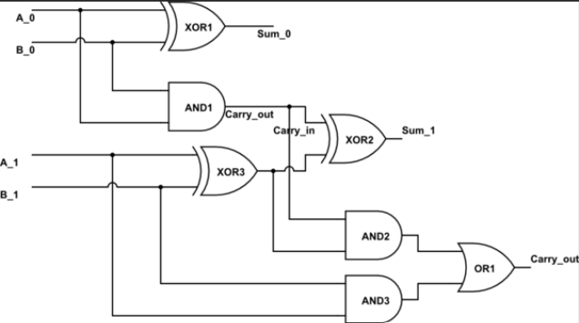
This is how digital multipliers work in CPUs!
Summary
Combinational circuits are the workhorses of digital electronics:
✅ MUX: Selects one input from many
✅ DEMUX: Distributes one input to many outputs
✅ Decoder: Binary code → One-hot representation
✅ Encoder: One-hot → Binary code
✅ Comparator: Compares binary numbers
✅ Parity: Simple error detection
Key Takeaways:
- No Memory: Output depends only on current inputs
- Building Blocks: MUX, decoder, encoder are fundamental
- Universal: MUX can implement any Boolean function
- Practical: Used everywhere in digital systems
- Cascadable: Can combine smaller units to build larger ones
We've mastered combinational logic where output depends only on inputs. Next, we'll add memory to create sequential circuits with flip-flops—enabling circuits that remember!
Further Reading
- Datasheet study: 74HC series combinational ICs
- Karnaugh maps for larger circuit simplification
- Quine-McCluskey for systematic minimization
- HDL implementation of combinational circuits
Practice Problems:
- Design an 8:1 MUX using two 4:1 MUXes
- Implement a full adder using only a 4:1 MUX
- Create truth table for 8-to-3 priority encoder
- Design a 2-bit comparator from scratch
- How many 2:4 decoders needed to build a 4:16 decoder?
- Implement XOR using a 2:1 MUX
- Design odd parity checker for 4-bit data