Boolean Algebra and Truth Tables
Introduction
Imagine trying to design a complex digital circuit without any mathematical foundation—like building a skyscraper without understanding physics. That's where Boolean algebra comes in. It's the mathematical language of digital electronics, invented by George Boole in 1854, long before computers existed!
Boolean algebra allows us to:
- Represent logic circuits mathematically
- Simplify complex circuits
- Prove that two circuits are equivalent
- Design efficient digital systems
Every digital device you use—from smartphones to computers to traffic lights—relies on Boolean algebra. Learning it gives you the power to design, analyze, and optimize digital circuits systematically.
The Basics: Binary Logic
Unlike regular algebra that works with numbers, Boolean algebra works with just two values:
- TRUE (1, HIGH, ON)
- FALSE (0, LOW, OFF)
These two states can represent:
- Voltage levels (5V vs 0V)
- Switch positions (ON vs OFF)
- Logical conditions (TRUE vs FALSE)
- Binary digits (1 vs 0)
Boolean Variables and Constants
Variables are represented by letters (A, B, C, X, Y, Z) and can have values 0 or 1.
Constants are fixed values:
- 0 (FALSE, LOW)
- 1 (TRUE, HIGH)
Example:
- If A = 1 and B = 0, what is A AND B?
- Answer: 0 (both must be 1 for AND to be true)
Truth Tables: The Universal Language
A truth table shows the output of a logic operation for every possible combination of inputs.
Truth Table Structure
For N inputs, there are 2^N possible combinations.
| Number of Inputs | Possible Combinations |
|---|---|
| 1 | 2¹ = 2 |
| 2 | 2² = 4 |
| 3 | 2³ = 8 |
| 4 | 2⁴ = 16 |
| N | 2^N |
Standard Format:
[Diagram: Generic truth table structure showing:
- Input columns (A, B, C...)
- Vertical separator line
- Output column(s) (Y, Z...)
- Rows showing all possible input combinations in binary order (000, 001, 010...)]
Basic Boolean Operations
1. NOT Operation (Inversion)
Symbol: Ā, A', ~A, or ¬A
Logic Gate: Inverter
The NOT operation flips the value:
| A | Ā |
|---|---|
| 0 | 1 |
| 1 | 0 |
Boolean Expression: Y = Ā

Real-World Example:
- If a door sensor is 1 when closed, NOT makes it 1 when open
- Used to invert logic levels
2. AND Operation
Symbol: ·, ∧, or simply AB
Logic Gate: AND gate
Output is 1 only when ALL inputs are 1:
| A | B | A · B |
|---|---|---|
| 0 | 0 | 0 |
| 0 | 1 | 0 |
| 1 | 0 | 0 |
| 1 | 1 | 1 |
Boolean Expression: Y = A · B or Y = AB

Real-World Examples:
- Safety interlock: Machine runs only when guard is closed AND start button pressed
- Password system: Access granted only when username correct AND password correct
Think of AND as a series circuit: Current flows only when ALL switches are closed.
3. OR Operation
Symbol: +, ∨
Logic Gate: OR gate
Output is 1 when AT LEAST ONE input is 1:
| A | B | A + B |
|---|---|---|
| 0 | 0 | 0 |
| 0 | 1 | 1 |
| 1 | 0 | 1 |
| 1 | 1 | 1 |
Boolean Expression: Y = A + B

Real-World Examples:
- Alarm system: Alarm triggers if front door OR back door opened
- Multiple switches: Light turns on from switch 1 OR switch 2
Think of OR as a parallel circuit: Current flows when ANY switch is closed.
4. NAND Operation (NOT-AND)
Symbol: ⊼ or (AB)'
Logic Gate: NAND gate
NAND is AND followed by NOT. Output is 0 only when ALL inputs are 1:
| A | B | A NAND B |
|---|---|---|
| 0 | 0 | 1 |
| 0 | 1 | 1 |
| 1 | 0 | 1 |
| 1 | 1 | 0 |
Boolean Expression: Y = (A · B)' or Y = A NAND B

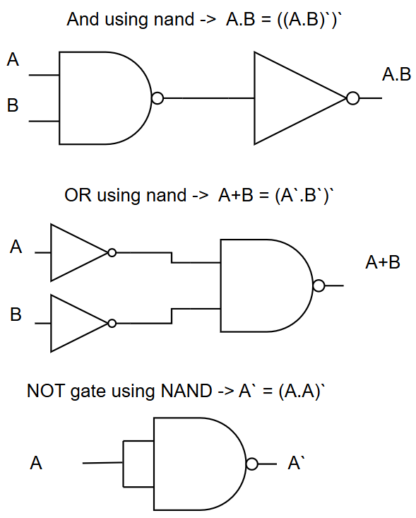
NAND is called a "universal gate" because ANY logic function can be built using only NAND gates! This makes it extremely important in IC design.
5. NOR Operation (NOT-OR)
Symbol: ⊽ or (A+B)'
Logic Gate: NOR gate
NOR is OR followed by NOT. Output is 1 only when ALL inputs are 0:
| A | B | A NOR B |
|---|---|---|
| 0 | 0 | 1 |
| 0 | 1 | 0 |
| 1 | 0 | 0 |
| 1 | 1 | 0 |
Boolean Expression: Y = (A + B)' or Y = A NOR B

Like NAND, NOR is also a universal gate—you can build any logic function using only NOR gates!
6. XOR Operation (Exclusive-OR)
Symbol: ⊕
Logic Gate: XOR gate
Output is 1 when inputs are DIFFERENT (one but not both):
| A | B | A ⊕ B |
|---|---|---|
| 0 | 0 | 0 |
| 0 | 1 | 1 |
| 1 | 0 | 1 |
| 1 | 1 | 0 |
Boolean Expression: Y = A ⊕ B = A'B + AB'

Real-World Examples:
- Two-way light switch (either switch can toggle the light)
- Error detection in digital communication
- Binary addition (sum bit)
XOR is 1 when inputs are different, 0 when they're the same. Think: "one or the other, but not both."
7. XNOR Operation (Exclusive-NOR)
Symbol: ⊙ or ⊕̅
Logic Gate: XNOR gate
XNOR is XOR followed by NOT. Output is 1 when inputs are the SAME:
| A | B | A ⊙ B |
|---|---|---|
| 0 | 0 | 1 |
| 0 | 1 | 0 |
| 1 | 0 | 0 |
| 1 | 1 | 1 |
Boolean Expression: Y = (A ⊕ B)' or Y = A'B' + AB

Real-World Example:
- Equality checker: Output 1 when two bits are equal
- Used in error detection (parity checking)
Boolean Algebra Laws and Theorems
Just like regular algebra has rules (like a + 0 = a), Boolean algebra has its own laws:
Basic Laws
| Law Name | AND Form | OR Form |
|---|---|---|
| Identity | A · 1 = A | A + 0 = A |
| Null/Dominance | A · 0 = 0 | A + 1 = 1 |
| Idempotent | A · A = A | A + A = A |
| Inverse | A · Ā = 0 | A + Ā = 1 |
| Involution | (Ā)' = A | (Ā)' = A |
Examples:
- Identity: ORing with 0 doesn't change:
A + 0 = A - Null: ANDing with 0 always gives 0:
A · 0 = 0 - Idempotent: ANDing a signal with itself:
A · A = A - Inverse: A signal ANDed with its complement:
A · Ā = 0
Commutative Laws
Order doesn't matter:
- A · B = B · A
- A + B = B + A
Practical Meaning: You can swap the inputs to an AND or OR gate without changing the output.
Associative Laws
Grouping doesn't matter:
- (A · B) · C = A · (B · C)
- (A + B) + C = A + (B + C)
Practical Meaning: When cascading gates, the order of grouping doesn't matter.
Distributive Laws
AND distributes over OR:
- A · (B + C) = (A · B) + (A · C)
OR distributes over AND:
- A + (B · C) = (A + B) · (A + C)
Practical Example:
A · (B + C) = (A · B) + (A · C)

Can be used to simplify or factor expressions
De Morgan's Theorems
These are CRITICALLY important for circuit simplification:
First Theorem:
The complement of AND is OR of complements
Second Theorem:
The complement of OR is AND of complements
Extended Form:
- (A · B · C)' = Ā + B̄ + C̄
- (A + B + C)' = Ā · B̄ · C̄
Verification with Truth Table:
| A | B | A·B | (A·B)' | Ā | B̄ | Ā+B̄ |
|---|---|---|---|---|---|---|
| 0 | 0 | 0 | 1 | 1 | 1 | 1 |
| 0 | 1 | 0 | 1 | 1 | 0 | 1 |
| 1 | 0 | 0 | 1 | 0 | 1 | 1 |
| 1 | 1 | 1 | 0 | 0 | 0 | 0 |
Notice: (A·B)' column equals Ā+B̄ column! ✓
To apply De Morgan's:
- Break the bar (complement)
- Change the operation (AND ↔ OR)
- Complement each variable
Example: (A · B · C)' → Ā + B̄ + C̄
Absorption Laws
- A + (A · B) = A
- A · (A + B) = A
Practical Use: Eliminate redundant terms in expressions.
Consensus Theorem
- A·B + Ā·C + B·C = A·B + Ā·C
The term B·C is redundant and can be eliminated.
Circuit Simplification Example
Problem: Simplify Y = A·B + A·B̄
Solution:
Y = A·B + A·B̄
Y = A·(B + B̄)    [Distributive law]
Y = A·(1)        [Inverse law: B + B̄ = 1]
Y = A            [Identity law: A·1 = A]
Result: The complex expression simplifies to just A!
Creating Truth Tables from Boolean Expressions
Problem: Create truth table for Y = A·B̄ + Ā·C
Step 1: Identify all variables: A, B, C (3 variables = 8 rows)
Step 2: List all input combinations
Step 3: Evaluate intermediate terms
Step 4: Evaluate final expression
| A | B | C | B̄ | A·B̄ | Ā | Ā·C | Y = A·B̄ + Ā·C |
|---|---|---|---|---|---|---|---|
| 0 | 0 | 0 | 1 | 0 | 1 | 0 | 0 |
| 0 | 0 | 1 | 1 | 0 | 1 | 1 | 1 |
| 0 | 1 | 0 | 0 | 0 | 1 | 0 | 0 |
| 0 | 1 | 1 | 0 | 0 | 1 | 1 | 1 |
| 1 | 0 | 0 | 1 | 1 | 0 | 0 | 1 |
| 1 | 0 | 1 | 1 | 1 | 0 | 0 | 1 |
| 1 | 1 | 0 | 0 | 0 | 0 | 0 | 0 |
| 1 | 1 | 1 | 0 | 0 | 0 | 0 | 0 |
Creating Boolean Expressions from Truth Tables
Sum of Products (SOP) Method
Minterm Method: Focus on rows where output is 1.
Example: Create expression for this truth table:
| A | B | Y |
|---|---|---|
| 0 | 0 | 0 |
| 0 | 1 | 1 |
| 1 | 0 | 1 |
| 1 | 1 | 0 |
Step 1: Find rows where Y = 1
- Row 2: A=0, B=1 → minterm = Ā·B
- Row 3: A=1, B=0 → minterm = A·B̄
Step 2: OR the minterms together
Simplification Check: This is actually the XOR function! Y = A ⊕ B
Product of Sums (POS) Method
Maxterm Method: Focus on rows where output is 0.
Using the same truth table:
Step 1: Find rows where Y = 0
- Row 1: A=0, B=0 → maxterm = (A + B)
- Row 4: A=1, B=1 → maxterm = (Ā + B̄)
Step 2: AND the maxterms together
- SOP (Sum of Products): OR of AND terms, easier to implement with AND-OR gates
- POS (Product of Sums): AND of OR terms, sometimes more efficient
Choose based on which gives simpler expression or better matches available gates.
Practical Application Example
Scenario: Design a burglar alarm system
Requirements:
- Door sensor (D): 1 when door open
- Window sensor (W): 1 when window open
- System armed (S): 1 when armed
- Alarm (A): Should sound if system armed AND (door OR window opened)
Boolean Expression:
Expanded Form:
Truth Table:
| S | D | W | A |
|---|---|---|---|
| 0 | 0 | 0 | 0 |
| 0 | 0 | 1 | 0 |
| 0 | 1 | 0 | 0 |
| 0 | 1 | 1 | 0 |
| 1 | 0 | 0 | 0 |
| 1 | 0 | 1 | 1 |
| 1 | 1 | 0 | 1 |
| 1 | 1 | 1 | 1 |
Common Pitfalls and Tips
-
Confusing AND with OR:
- AND: ALL must be true
- OR: AT LEAST ONE must be true
-
Incorrect De Morgan's Application:
- ❌ (A·B)' = Ā·B̄ (WRONG)
- ✓ (A·B)' = Ā + B̄ (CORRECT)
-
Forgetting to complement individual variables:
- (A+B)' ≠ A'+B'
- (A+B)' = A'·B' ✓
- Look for common factors (use distributive law)
- Apply De Morgan's to convert between AND/OR
- Use consensus theorem to eliminate redundant terms
- Check with truth table if unsure
- Practice! Simplification gets easier with experience
Boolean Algebra in Modern Digital Design
Today's digital design uses Boolean algebra extensively:
Hardware Description Languages (HDL):
// Verilog example
assign Y = (A & B) | (~A & C);  // Boolean expression directly in code
Software (C/C++):
// Bitwise operations follow Boolean algebra
result = (a && b) || (!a && c);
Circuit Synthesis Tools: Modern FPGA and ASIC tools automatically:
- Simplify Boolean expressions
- Optimize gate count
- Minimize propagation delay
- Use Boolean algebra rules internally
Summary
Boolean algebra is the mathematical foundation of all digital electronics. Master these concepts and you can:
✅ Design logic circuits systematically
✅ Simplify complex circuits
✅ Convert between different representations
✅ Prove circuit equivalence
✅ Debug digital systems effectively
Key Takeaways:
- Two Values: Everything is 0 or 1, FALSE or TRUE
- Basic Operations: NOT, AND, OR are fundamental
- Universal Gates: NAND and NOR can build anything
- De Morgan's Theorems: Critical for simplification
- Truth Tables: Universal way to describe logic functions
- Simplification: Use Boolean laws to reduce complexity
With Boolean algebra mastered, we're ready to design real combinational circuits like multiplexers, decoders, and encoders—the building blocks of digital systems!
Further Reading
- "Digital Design" by Morris Mano
- "Fundamentals of Digital Logic" by Brown and Vranesic
- Karnaugh Maps for advanced simplification
- Quine-McCluskey algorithm for systematic minimization
Practice Problems:
- Simplify: Y = A·B + A·B̄ + Ā·B
- Apply De Morgan's: (A + B·C)'
- Create truth table for: Y = (A ⊕ B) · C
- Prove using truth table: A + A·B = A
- Design a circuit: "Output 1 if exactly two of three inputs are 1"
- Convert to POS form: Y = A·B̄ + Ā·C
- Implement XOR using only NAND gates