🌊 Oscillator Circuits: Generating Signals
We've seen the 555 timer generate square waves. But what if you need:
- Sine waves (pure tones, signal sources)
- Triangle waves (audio synthesis, test signals)
- Precise frequencies (quartz crystal accuracy)
- Low distortion (audio, communications)
This is where oscillator circuits come in.
🎯 What is an Oscillator?
An oscillator is a circuit that converts DC power into AC signal.
Key Requirements
For sustained oscillation, we need:
- Amplification (gain > 1)
- Positive feedback (output fed back to input)
- Frequency-selective network (determine oscillation frequency)
- Startup mechanism (noise or turn-on transient)
Barkhausen Criterion for oscillation:
Where:
- = amplifier gain
- = feedback factor
- Product must equal 1 at the oscillation frequency
- Phase shift must be 0° (or 360°)
📊 Types of Oscillators
| Type | Waveform | Frequency Range | Key Component | Application |
|---|---|---|---|---|
| RC Oscillator | Sine | 1 Hz - 1 MHz | RC network | Audio, function generators |
| LC Oscillator | Sine | 100 kHz - 100 MHz | LC tank | RF, radio transmitters |
| Crystal Oscillator | Square/sine | 32 kHz - 200 MHz | Quartz crystal | Clocks, microcontrollers |
| Relaxation Oscillator | Triangle/square | 1 Hz - 1 MHz | Comparator + integrator | Function generators |
🎵 RC Oscillators: Wien Bridge
The Wien Bridge Oscillator produces high-quality sine waves using an op-amp and RC network.
The Circuit
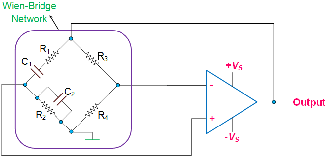
- Op-amp in non-inverting configuration
- Series RC (R1, C1) from output to non-inverting input
- Parallel RC (R2, C2) from non-inverting input to ground
- Negative feedback through voltage divider (R3, R4) with diode limiting
- R1 = R2 = R, C1 = C2 = C (for simplicity)
How It Works
Positive feedback through RC network:
- At one specific frequency, phase shift = 0°
- Feedback factor = 1/3
- Op-amp gain must = 3 for oscillation
Frequency determination:
For equal Rs and Cs (simplest case).
Required gain:
Set by: , so
🎚️ Design Example: 1 kHz Sine Wave Generator
Goal: Generate 1 kHz sine wave
Design:
Choose (standard value for audio)
Calculate :
Use standard value:
Set gain = 3:
Problem: Fixed gain = 3 is hard to achieve perfectly.
- Too low → oscillation dies
- Too high → distortion (clipping)
Solution: Use automatic gain control (AGC):
- Add diodes or FETs in feedback path
- As amplitude increases, effective resistance changes
- Self-stabilizes at desired amplitude
💡 Amplitude Stabilization
Diode Clipping Method

- Back-to-back diodes in parallel with R3
- When output swing exceeds diode drop, gain reduces
- Maintains stable amplitude
Advantages:
- Simple
- Self-regulating
- Low cost
Disadvantage:
- Some distortion (diodes clip)
FET/Thermistor Method
Use a component whose resistance changes with signal level:
- JFET: Resistance ↑ as gate voltage ↑
- Thermistor: Resistance changes with heating
- Incandescent lamp: Resistance ↑ with current
Result: Low-distortion, stable sine wave!
- Low distortion (<1% with good AGC)
- Simple design (few components)
- Tunable (variable R or C)
- Audio frequencies (1 Hz to 100 kHz)
Perfect for audio test equipment and function generators!
📐 LC Oscillators: Colpitts and Hartley
For higher frequencies (RF, radio), use LC tank circuits.
Why LC at High Frequencies?
- RC networks have too much loss at MHz ranges
- LC tanks have high Q (quality factor)
- Better frequency stability
- Lower phase noise
🔄 Colpitts Oscillator
Uses a capacitive voltage divider in the tank circuit.
- Transistor (BJT or FET)
- Inductor L from collector to Vcc
- Two capacitors C1, C2 in series from collector to ground
- Feedback from C1-C2 junction to base
- Bias resistors
Frequency
Where:
(Series combination of C1 and C2)
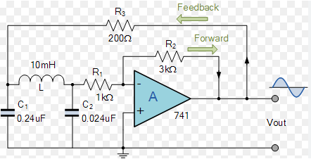
🔀 Hartley Oscillator
Uses an inductive voltage divider (tapped inductor).
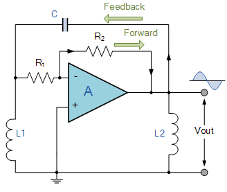
- Two inductors L1, L2 in series
- Single capacitor C
- Feedback from inductor tap
Frequency
Advantage: Easy to tap inductor center for feedback
💎 Crystal Oscillators: Ultimate Precision
For precise frequency (clocks, communications), use quartz crystals.
Why Crystals?
Quartz crystals have:
- Very high Q (10,000 to 100,000+)
- Excellent stability (±10 ppm or better)
- Low temperature drift
- No tuning required
How Crystals Work
Quartz is piezoelectric:
- Mechanical vibration → electrical signal
- Electrical signal → mechanical vibration
Resonance occurs at a precise frequency determined by:
- Crystal cut
- Physical dimensions
- Temperature
🔌 Pierce Oscillator (Crystal)
The most common crystal oscillator circuit.
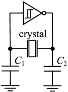
- Crystal between inverter input and output
- Two capacitors (C1, C2) to ground
- Feedback resistor in parallel with crystal
- Forms self-sustaining oscillation at crystal frequency
Used in:
- Microcontroller clock inputs
- RTC (Real-Time Clock) modules
- Communication equipment
- GPS receivers
Common Crystal Frequencies
| Frequency | Application |
|---|---|
| 32.768 kHz | RTC (Real-Time Clocks) - divides to 1 Hz |
| 8 MHz | Microcontrollers |
| 12 MHz | USB devices |
| 16 MHz | Arduino boards |
| 25 MHz | Ethernet |
| 27 MHz | Old RC toys |
⚡ Design Example: 16 MHz Microcontroller Clock
Goal: Generate stable 16 MHz clock for ATmega328P (Arduino)
Circuit:
- 16 MHz crystal
- Two 22pF ceramic capacitors to ground
- Connects to microcontroller XTAL1 and XTAL2 pins
- Internal inverter in MCU provides gain
Result:
- Precise timing for UART, SPI, I2C
- Accurate delays and timekeeping
- Low jitter (phase noise)
Crystals are fragile!
- Avoid mechanical shock
- Don't overheat during soldering
- Use appropriate load capacitors (see datasheet)
- Keep traces short
- Ground plane under crystal
🌀 Relaxation Oscillators
Not sine waves, but triangle and square waves using comparators and integrators.
Basic Relaxation Oscillator
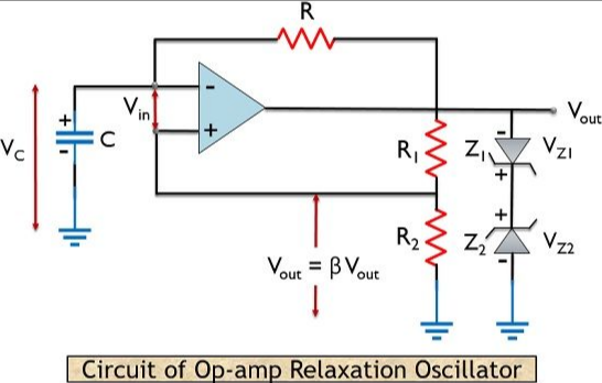
- Op-amp comparator with hysteresis (Schmitt trigger)
- RC integrator
- Output toggles when thresholds reached
- Produces triangle wave at capacitor, square wave at output
Operation
- Comparator output HIGH → capacitor charges up
- Voltage exceeds upper threshold → comparator flips to LOW
- Capacitor charges down
- Voltage falls below lower threshold → comparator flips to HIGH
- Repeat!
Result:
- Square wave at comparator output
- Triangle wave at capacitor
🎛️ Function Generator (All-in-One)
Combine techniques to generate sine, square, and triangle waves simultaneously!
Basic Function Generator Circuit
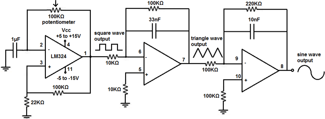
- Relaxation oscillator → triangle wave
- Comparator → square wave (from triangle)
- Triangle-to-sine shaper → sine wave
Triangle-to-Sine Shaping:
- Use diode shaping network
- Or differential amplifier
- Approximates sine from triangle
📊 Oscillator Performance Metrics
Frequency Stability
How much frequency changes with:
- Temperature: ppm/°C (parts per million per degree)
- Supply voltage: %/V
- Load: %/change in load
- Aging: ppm/year
Example:
- RC oscillator: 100-10,000 ppm/°C
- Crystal oscillator: 1-50 ppm/°C (TCXO: 0.1-5 ppm/°C)
Phase Noise
Random fluctuations in phase/frequency.
Important for:
- RF communications
- Data clocks
- ADC sampling clocks
Harmonics and Distortion
How "pure" is the sine wave?
THD (Total Harmonic Distortion):
- Wien bridge with AGC: <1%
- LC oscillator: 1-5%
- Relaxation oscillator shaped: 5-10%
🔬 Oscillator Comparison Table
| Oscillator Type | Freq. Stability | Distortion | Complexity | Cost | Best For |
|---|---|---|---|---|---|
| RC (Wien) | Poor | Low | Medium | Low | Audio test equipment |
| LC (Colpitts) | Good | Medium | Medium | Medium | RF local oscillators |
| Crystal | Excellent | N/A* | Low | Medium | Digital clocks, MCUs |
| Relaxation | Poor | N/A** | Low | Very Low | Function generators |
*Square wave output, not sine
**Non-sinusoidal by design
🛠️ Practical Design Tips
For RC Oscillators (Wien Bridge)
- Use 1% tolerance resistors (or better)
- Use low-loss capacitors (film, C0G)
- Implement AGC for amplitude stability
- Use low-noise op-amp (TL07x, OPA134)
- Shield from temperature variations
For LC Oscillators
- Use high-Q inductors (air-core or ferrite)
- Match capacitors well
- Keep layout symmetrical
- Minimize stray capacitance
- Use temperature-stable components
For Crystal Oscillators
- Follow datasheet for load capacitance
- Keep traces short (<1 inch)
- Use ground plane under crystal
- Shield from noise sources
- Don't overdrive crystal (check specifications)
🧪 Lab Exercise 1: Build a Wien Bridge Oscillator
Objective: Generate 1 kHz sine wave
Components:
- TL072 dual op-amp
- 1.6kΩ resistors × 2
- 100nF capacitors × 2
- 10kΩ, 20kΩ for gain setting
- Back-to-back 1N4148 diodes for AGC
- ±12V power supply
Steps:
- Build circuit on breadboard
- Power up and observe self-starting oscillation
- Measure frequency with oscilloscope
- Observe waveform quality (distortion)
- Vary R or C to change frequency
- Add/remove AGC diodes to see effect
Measurements:
- Frequency: Should be ~1 kHz
- Amplitude: Typically 10-20Vpp (±supply dependent)
- Distortion: Observe with spectrum analyzer or FFT
🧪 Lab Exercise 2: Crystal Oscillator Test
Objective: Build and test 8 MHz crystal oscillator
Components:
- 8 MHz crystal
- 74HC04 hex inverter (one gate used)
- 22pF capacitors × 2
- 1MΩ feedback resistor
- 5V power supply
Steps:
- Build Pierce oscillator configuration
- Power up
- Measure frequency with frequency counter
- Observe square wave with oscilloscope
- Check rise/fall times
- Verify frequency accuracy
Analysis:
- Is frequency exactly 8.000 MHz?
- What's the frequency error in ppm?
- How does it compare to RC oscillator?
✅ Key Takeaways
- RC oscillators (Wien Bridge) for audio sine waves
- LC oscillators (Colpitts, Hartley) for RF
- Crystal oscillators for precision and stability
- Relaxation oscillators for triangle/square waves
- AGC is critical for amplitude stability
- Component quality affects performance
- Crystal = best stability, RC = most flexible
🎓 Looking Ahead
Oscillators are fundamental building blocks:
- PLLs (Phase-Locked Loops) use oscillators
- Frequency synthesizers build on oscillator concepts
- Clock generation in digital systems
- Signal sources for testing and measurement
Next, we'll explore Wheatstone bridges - another analog measurement circuit!
📚 Further Study
- Build different oscillator types and compare
- Measure frequency stability vs. temperature
- Use spectrum analyzer to check harmonic content
- Design variable-frequency oscillator (VFO)
- Research VCXO (Voltage-Controlled Crystal Oscillator)
- Study DDS (Direct Digital Synthesis) as modern alternative