🎛️ Active Filters: Shaping Signals with Precision
In the Fundamentals section, we learned about passive RC filters. They work, but they have limitations:
- Loading effects (output impedance changes frequency response)
- No gain (only attenuation)
- Limited sharpness (gentle roll-off)
Active filters solve all these problems using op-amps.
🔍 Why Active Filters?
| Feature | Passive Filter | Active Filter |
|---|---|---|
| Gain | Always < 1 | Can be > 1 |
| Loading | Sensitive to load | Buffered output |
| Roll-off | 20dB/decade max | Can be steeper |
| Tuning | Hard (component interaction) | Easier (independent controls) |
| Size | Large inductors needed for LF | No inductors! |
| Cost | Low | Moderate |
🎯 Filter Basics Refresher
What Filters Do
- Pass certain frequencies
- Reject (attenuate) others
Four Basic Types
- Low-Pass Filter (LPF): Passes low frequencies, blocks high frequencies
- High-Pass Filter (HPF): Passes high frequencies, blocks low frequencies
- Band-Pass Filter (BPF): Passes a band of frequencies
- Band-Stop Filter (BSF): Blocks a band of frequencies (notch filter)
📊 Key Filter Parameters
Cutoff Frequency ()
The frequency where output is -3dB (0.707× or 70.7%) of passband value.
Roll-off Rate
How quickly the filter attenuates outside the passband.
- 1st order: 20dB/decade
- 2nd order: 40dB/decade
- 3rd order: 60dB/decade
Quality Factor (Q)
Determines the sharpness of the response (important for band-pass filters).
📉 First-Order Low-Pass Filter
The Circuit
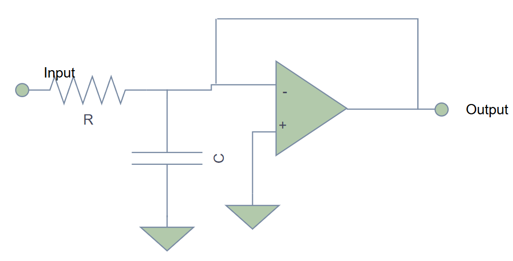
The Math
Cutoff frequency:
Gain at DC: Set by resistor divider (typically 1 for unity-gain)
Frequency response:
At : Output is 0.707× input (−3dB)
Roll-off: 20dB/decade above
🎚️ Design Example: Audio Subwoofer Filter
Goal: Pass frequencies below 200Hz, reject above
Design:
- Choose (common value)
Calculate :
Use standard value:
Result: Clean bass signal with treble removed!
For audio filters:
- Film capacitors (polypropylene): Best for audio quality
- Ceramic capacitors (X7R/C0G): Good for general use, cheaper
- Avoid electrolytics in signal path (use for power supply filtering only)
📈 First-Order High-Pass Filter
The Circuit
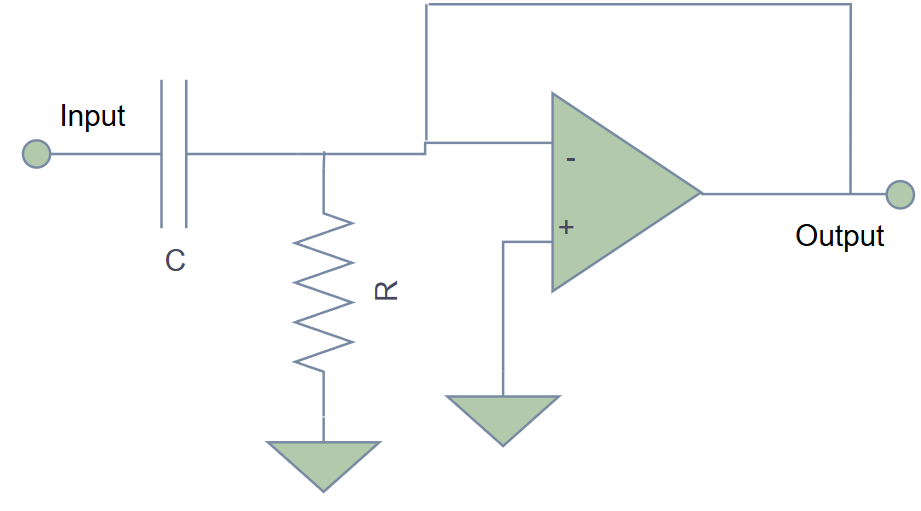
The Math
Cutoff frequency:
Frequency response:
At : Output is 0.707× input (−3dB)
Roll-off: 20dB/decade below
🎤 Design Example: Microphone AC Coupling
Goal: Remove DC offset, pass audio (20Hz and above)
Design:
- Choose (high impedance for low noise)
Calculate :
Use standard value: or
Result: DC blocked, audio passes cleanly!
🎯 Second-Order Filters: Steeper is Better
First-order filters are gentle. For sharper filtering, we need second-order (or higher).
Advantages
- 40dB/decade roll-off (twice as steep)
- Better separation between pass and stop bands
- More design control
Popular Topologies
- Sallen-Key (voltage-controlled)
- Multiple Feedback (MFB)
- State Variable (versatile but complex)
We'll focus on Sallen-Key (most common).
📉 Second-Order Low-Pass Filter (Sallen-Key)
The Circuit
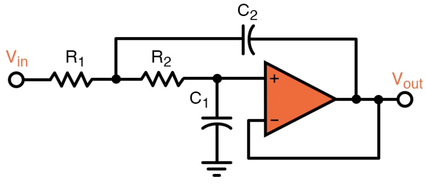
Design Equations
For Butterworth response (maximally flat):
Equal component values:
Cutoff frequency:
Op-amp gain: (for Butterworth)
Set using:
🔊 Design Example: Anti-Aliasing Filter
ADC sampling: 10kHz
Anti-aliasing filter: (Nyquist = 5kHz)
Design:
- Choose
- Calculate:
- Use
- Set gain: using ,
Result: Sharp cutoff prevents aliasing, signal integrity maintained!
Different applications need different responses:
| Type | Characteristic | Use Case |
|---|---|---|
| Butterworth | Maximally flat passband | General purpose |
| Chebyshev | Steeper roll-off, ripple in passband | When sharp cutoff needed |
| Bessel | Linear phase (no distortion) | Audio, data transmission |
📈 Second-Order High-Pass Filter (Sallen-Key)
The Circuit
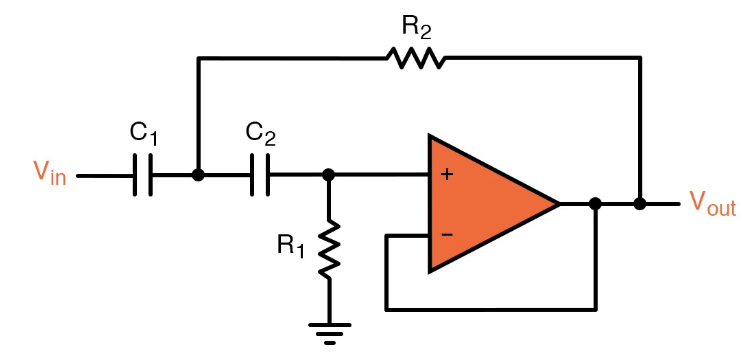
Design Equations
For Butterworth:
Cutoff frequency:
Op-amp gain:
📡 Design Example: Infrasonic Filter for Audio
Goal: Remove rumble and handling noise below 20Hz
Design:
- Choose (larger C for low frequency)
- Calculate:
- Use
- Set gain:
Result: Clean audio, no low-frequency rumble!
🎵 Band-Pass Filter
Combines high-pass and low-pass.
Two Approaches
1. Cascade (Simple)
HPF → LPF in series
Requirements:
Bandwidth:
2. Dedicated Band-Pass (MFB)
Single op-amp, optimized for narrow bands.
📻 Design Example: Voice Band Filter (300Hz - 3kHz)
Cascade approach:
HPF stage:
- ,
LPF stage:
- ,
Bandwidth:
Result: Perfect for voice communication, rejects noise outside speech range!
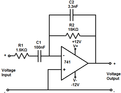
🚫 Band-Stop (Notch) Filter
Used to remove specific unwanted frequencies.
Common Application: 50/60Hz Mains Hum Removal
Twin-T Notch Filter:
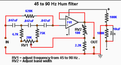
- Two T-networks (RC and CR) in parallel
- Op-amp buffer
Design for 50Hz notch:
- Choose
Result: Removes 50Hz hum while passing everything else!
🔬 Filter Design Process
Step-by-Step
-
Define Requirements
- Passband frequency range
- Stopband frequency range
- Attenuation needed
- Acceptable ripple
-
Choose Filter Type
- Butterworth (general)
- Chebyshev (steep roll-off)
- Bessel (phase linearity)
-
Determine Order
- 1st order: 20dB/decade
- 2nd order: 40dB/decade
- 3rd order: 60dB/decade
-
Select Topology
- Sallen-Key (most common)
- MFB (inverting, good CMRR)
- State variable (adjustable)
-
Calculate Components
- Use design equations
- Select standard values
- Verify cutoff frequency
-
Set Op-Amp Gain
- Butterworth: 1.586
- Unity gain: simpler but less sharp
-
Simulate & Test
⚡ Practical Design Tips
Resistor Selection
- Use 1% tolerance or better
- Typical range: 1kΩ to 100kΩ
- Avoid very high values (noise)
- Avoid very low values (loading)
Capacitor Selection
- Use film caps for precision
- C0G/NP0 ceramics for stability
- Typical range: 10pF to 1µF
- Match capacitors in pairs if possible
Op-Amp Selection
- Low noise: OPAx134, LT1028
- High speed: OPA684, AD8099
- General purpose: TL07x, LM358
- Precision: OPA2277, AD8628
Power Supply
- Use ±15V or ±12V for maximum headroom
- Single supply: Add DC offset (V/2)
- Decouple op-amp power pins
📊 Common Design Pitfalls
| Problem | Cause | Solution |
|---|---|---|
| Oscillation | Insufficient phase margin | Add small capacitor across feedback resistor |
| Noise | Poor grounding, layout | Star grounding, short traces |
| Distortion | Op-amp slew rate too low | Choose faster op-amp |
| DC offset drift | Temperature, bias current | Use precision op-amp or AC coupling |
| Wrong cutoff | Component tolerance | Measure and adjust, use trimmers |
🧪 Lab Exercise: Build a Tone Control
Objective: Create bass/treble control for audio
Circuit:
- Bass: 2nd-order LPF, adjustable cutoff (50-200Hz)
- Treble: 2nd-order HPF, adjustable cutoff (5kHz-20kHz)
- Summing amplifier: Combine bass + mid + treble
Components:
- Op-amps: TL072 (dual)
- Potentiometers for cutoff adjustment
- Film capacitors
- 1% resistors
Test:
- Apply music signal
- Observe frequency response on oscilloscope
- Measure cutoff frequencies
- Adjust for desired tone
✅ Key Takeaways
- Active filters use op-amps for gain and buffering
- 1st order: 20dB/decade, simple but gentle
- 2nd order: 40dB/decade, sharper transitions
- Sallen-Key is the most common topology
- Butterworth gives flat passband response
- Component selection greatly affects performance
- Higher-order filters = cascading 2nd-order sections
🎓 Looking Ahead
Active filters are essential for:
- Data acquisition (anti-aliasing)
- Audio processing (equalizers, crossovers)
- Communications (channel selection)
- Control systems (noise rejection)
- Instrumentation (signal conditioning)
Next, we'll explore instrumentation amplifiers which often include built-in filtering!
📚 Further Resources
- Calculate filter designs: Online filter calculators (e.g., Analog Devices Filter Wizard)
- Simulate circuits: LTSpice, TINA-TI
- Study filter response: Plot magnitude and phase
- Experiment with different topologies and orders