🧮 Op-Amp Applications: Mathematical Operations
We've learned the basics of op-amps. Now let's see how they can perform actual math operations on signals.
These circuits don't just amplify. They add, subtract, integrate, and differentiate.
And they do it continuously, in real-time, with analog voltages.
➕ Summing Amplifier – Adding Voltages
The Problem
You have multiple input signals and need their weighted sum.
Examples:
- Audio mixing
- Multi-sensor averaging
- Control systems
The Circuit
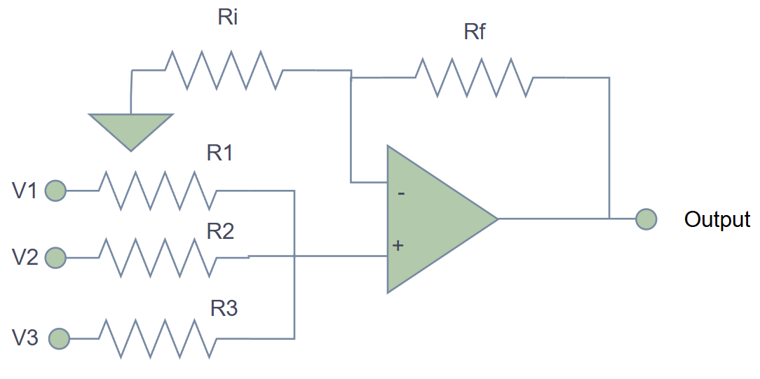
The Math
Using virtual ground at the inverting input:
Simple Case: Equal Resistors
If and :
Perfect adder! (with inversion)
🎚️ Weighted Summing Example
Audio mixer with 3 channels:
- Voice: ,
- Music: , (quieter)
- Effects: , (background)
With :
Each channel has its own "volume control" via resistor selection!
The summing amplifier is the heart of analog audio mixers. Professional mixing consoles use hundreds of these circuits.
➖ Difference Amplifier – Subtracting Voltages
The Problem
You need
Why?
- Sensor differential measurements
- Noise cancellation
- Bridge circuits
The Circuit
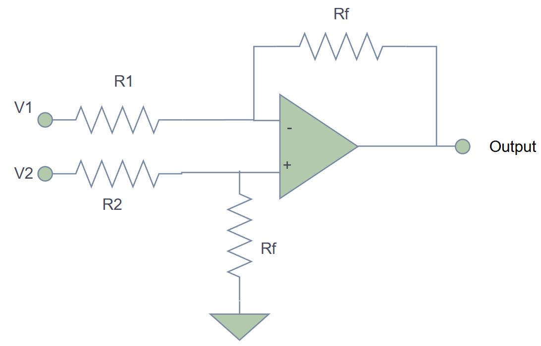
The Math
For a unity-gain difference amplifier where :
Perfect subtraction!
General Case (with gain)
If and :
You get amplified difference.
🌡️ Temperature Differential Example
Two temperature sensors:
- Sensor A: (Room temp)
- Sensor B: (Near heat source)
Difference amplifier with gain = 10:
Now your ADC can easily measure the temperature difference with high resolution!
The difference amplifier is sensitive to resistor matching. Use 1% tolerance resistors or better for accurate subtraction.
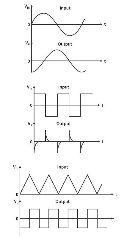
📈 Integrator – The Accumulator
What It Does
The output is the time integral (accumulation) of the input.
If input is constant → output ramps linearly
If input is zero → output holds value
If input reverses → output ramps in opposite direction
The Circuit
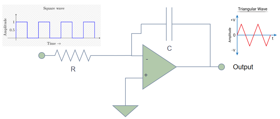
The Math
Simpler Understanding
The rate of change of output voltage:
- Positive input → output ramps down
- Negative input → output ramps up
- Larger input → faster ramp
⚡ Integrator Example: Converting Current to Voltage
Current source: (constant)
Integrator with , :
Time constant:
After 5ms:
Perfect for measuring total charge!
🎯 Real Applications of Integrators
| Application | Why Integration? |
|---|---|
| Charge amplifier | Convert sensor current to voltage |
| Waveform generation | Convert square wave → triangle wave |
| Control systems | PI controllers need integration |
| Analog computers | Solving differential equations |
| Signal processing | Area under curve measurement |
Real integrators drift due to:
- Op-amp input bias current
- DC offsets
Solution: Add a large resistor (MΩ range) in parallel with capacitor to provide DC feedback without affecting AC integration.
📉 Differentiator – The Rate Detector
What It Does
Output is proportional to the rate of change of input.
Slow changes → small output
Fast changes → large output
Constant input → zero output
The Circuit
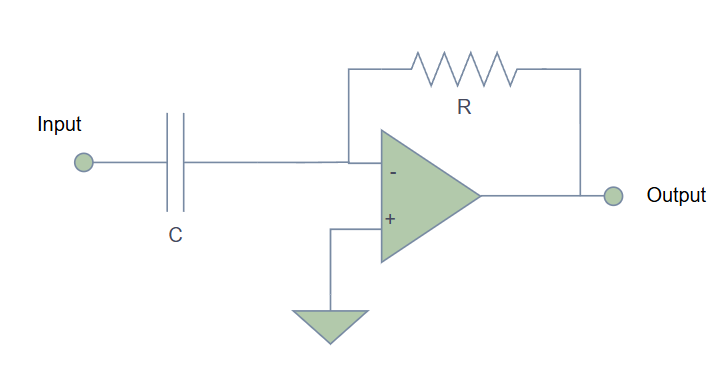
The Math
The output is the derivative (rate of change) of the input!
🏃 Differentiator Example: Edge Detection
Input: Square wave ( step in 1μs)
Differentiator with , :
At the rising edge, you get a sharp spike!
This is how edge detectors work.
⚠️ Problem with Practical Differentiators
Differentiators amplify noise.
Why?
High-frequency noise has rapid changes → large derivatives → huge noise at output.
Solution
Add a small resistor in series with the capacitor to limit high-frequency gain.
(Add a small resistor (100Ω - 1kΩ) in series with the input capacitor to limit high-frequency gain and prevent instability)
This creates a band-pass differentiator that works on your signal frequencies but ignores high-frequency noise.
🎯 Real Applications of Differentiators
| Application | Why Differentiation? |
|---|---|
| Velocity from position | Rate of change = speed |
| Edge detection | Find transitions in signals |
| High-pass filtering | Block DC, pass AC changes |
| Frequency doubling | In FM demodulation |
| Acceleration sensing | Rate of velocity change |
Differentiators are inherently unstable and noisy in pure form. Always add damping (series resistor) in practical circuits.
📊 Comparison Table
| Circuit | Function | Input-Output Relationship | Key Component |
|---|---|---|---|
| Summing Amplifier | Addition | Multiple input resistors | |
| Difference Amplifier | Subtraction | Balanced resistor network | |
| Integrator | Accumulation | Feedback capacitor | |
| Differentiator | Rate of change | Input capacitor |
🔬 Design Guidelines
For Summing Amplifiers
- Use resistors in 1% tolerance range
- Keep input impedances similar (unless weighting is desired)
- Consider input bias current effects with high-value resistors
For Difference Amplifiers
- Match resistor ratios precisely (this is critical!)
- Use resistor networks for better matching
- Consider instrumentation amplifier for better CMRR
For Integrators
- Add parallel resistor for DC stability (typically 1-10 MΩ)
- Add reset switch to discharge capacitor
- Use low-leakage capacitors (polypropylene or polystyrene)
For Differentiators
- Always add series input resistor for stability
- Limit bandwidth to avoid noise amplification
- Consider using RC high-pass filter instead for simple applications
🧪 Lab Exercise Ideas
-
Build a 3-input audio mixer
- Use potentiometers for volume control
- Mix three audio sources
- Observe how resistor values affect mixing
-
Temperature difference monitor
- Use two temperature sensors
- Build difference amplifier
- Measure temperature gradient across a heatsink
-
Triangle wave generator
- Square wave input to integrator
- Observe triangle wave output
- Change RC values to modify frequency
-
Edge detector
- Practical differentiator circuit
- Square wave input
- Observe output spikes at edges
✅ Key Takeaways
- Summing amplifiers add multiple signals with individual gain control
- Difference amplifiers subtract signals and reject common-mode noise
- Integrators accumulate signals over time (area under curve)
- Differentiators detect rate of change (slope)
- Each circuit has practical limitations that must be addressed
- These form the basis of analog computers and signal processing
🎓 Looking Ahead
These mathematical operations are building blocks for:
- Active filters (our next topic!)
- Control systems (PID controllers)
- Analog signal processing
- Instrumentation amplifiers
- Waveform generators
Master these, and you're ready to design sophisticated analog systems! 🚀
📚 Further Reading
- Experiment with different RC time constants
- Try cascading integrators and differentiators
- Research analog computers (they used these extensively!)
- Look into practical considerations for precision applications