Signal and Power Filters — RC, LC, Pi, and Common-Mode — Keeping Noise Out and Signal In
If a ferrite bead is the bouncer at the door of your power rail, a filter is the entire security system. Every interface between your electronics and the outside world — power input, analog signal input, communication line — needs a filter designed for what it is filtering. A filter you forget is a highway for noise to enter your design. A filter you design wrong is a decoration that does nothing.
Why Filters Exist at System Boundaries
Noise enters a PCB primarily through two paths: power connectors and I/O connectors. Once inside, noise propagates through the power plane, through coupling between adjacent traces, and through shared ground return paths. Filtering at the boundary intercepts noise before it propagates anywhere. Trying to filter it after it has spread is like mopping the floor while the tap is running.
The EMC standards reflect this: CISPR 32 and FCC Part 15B both test conducted emissions (noise coming out of the power port) and radiated emissions (noise radiating off cables and the enclosure). Filtering at each connector boundary reduces both — conducted directly, and radiated by reducing the common-mode currents that drive cable antennas.
RC Low-Pass Filter
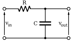
RC low-pass filter: f_c = 1/(2πRC). Simple, passive, no power required. Source: Wikimedia Commons, CC BY-SA

Formula
$$
f_c = \frac{1}{2\pi RC}
$$
The RC filter is the simplest filter: one resistor in series, one capacitor to ground. It rolls off at −20 dB per decade above the corner frequency. Cheap, small, requires no inductor.
Use Cases
- ADC input filtering: remove high-frequency noise and prevent aliasing before the ADC samples the signal
- Digital I/O debouncing: slow down the rising/falling edge of a mechanical switch to prevent multiple counts
- RESET pin filtering: prevent glitches from triggering a spurious reset
Worked Example — ADC Anti-Aliasing
Goal: Filter an analog sensor signal before a 12-bit ADC. Signal bandwidth: DC to 2 kHz. Cut off above 10 kHz to provide adequate attenuation before the Nyquist limit. ADC sample rate: 48 kSPS.
Choose C = 10 nF (a common, low-cost ceramic value):
$$
R = \frac{1}{2\pi \times 10,\text{kHz} \times 10,\text{nF}} = \frac{1}{6.28 \times 10^4 \times 10^{-8}} = 1{,}592,\Omega
$$
Use 1.5 kΩ (E24 standard value). Actual corner: 10.6 kHz — acceptable.
Trade-off: The 1.5 kΩ series resistor adds source impedance. If the sensor output impedance is also 1 kΩ, total source impedance is 2.5 kΩ — check the ADC datasheet for maximum allowed source impedance. For SAR ADCs, typically < 1 kΩ is recommended. If the sensor output impedance is high, buffer it with an op-amp before the RC filter.
LC Low-Pass Filter
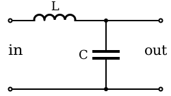
LC low-pass filter: steeper −40 dB/decade rolloff vs RC, no resistive power loss. Source: Wikimedia Commons, CC BY-SA

Why LC Instead of RC?
Two advantages: steeper rolloff (−40 dB/decade vs −20 dB/decade) and no power dissipation in the inductor (a resistor in series with a power rail wastes power as heat; an inductor does not, in theory).
The LC filter is the standard choice for switching regulator output filtering and power entry filtering where you cannot afford the voltage drop or power loss of a series resistor.
Formula
$$
f_c = \frac{1}{2\pi\sqrt{LC}}
$$
Worked Example — DC-DC Converter Output
Scenario: 5V DC-DC converter switching at 400 kHz. Output ripple must be < 10 mV peak-to-peak.
Design the LC corner at 10 kHz (two decades below the switching frequency gives > 40 dB attenuation of the switching ripple):
Choose L = 47 µH, solve for C:
$$
C = \frac{1}{(2\pi \times 10,\text{kHz})^2 \times 47,\mu\text{H}} = \frac{1}{(6.28 \times 10^4)^2 \times 4.7 \times 10^{-5}} = 5.4,\mu\text{F}
$$
Use 10 µF (next standard value, moves corner to 7.3 kHz — acceptable). Use a low-ESR MLCC or polymer capacitor.
Attenuation at 400 kHz (two decades above 7.3 kHz): 40 dB × 2 = −80 dB → ripple attenuation of 10,000× → well within spec.
The Damping Problem
An underdamped LC filter rings. At the resonant frequency, a sudden load transient causes the output to overshoot and oscillate — which can exceed ratings on sensitive ICs. Solutions:
- Add a small series resistance in the inductor path (damages the efficiency benefit slightly)
- Use a lossy inductor (inductors with ferrite core exhibit some resistance at high frequency)
- Add a damping RC network in parallel with C: R_d = √(L/C) / 2, C_d = 4 × C
Pi Filter (C-L-C)
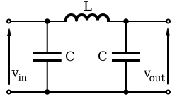
Pi (π) filter: best of both worlds — shunt input cap handles fast transients, series inductor blocks HF noise, shunt output cap provides local bypass. Source: Wikimedia Commons, CC BY-SA (C-L-C)

The Pi filter is a C-L-C network: one shunt capacitor before the inductor, one after. This gives:
- Better high-frequency attenuation than a single LC (effectively two LC stages)
- Input capacitor handles the noisy source; output capacitor handles the clean load
- The series inductor decouples the two capacitors so they work on different frequency ranges
Typical Values on a DC Power Input Connector
VIN_CONNECTOR → C1 (100nF, X7R) → GND
                      ↓
                 L1 (10µH, 0805, 500mA)
                      ↓
              C2 (100nF, X7R) → GND
                      ↓
                 TO BOARD POWER RAIL
C1 (100 nF): bypasses high-frequency noise on the connector side to ground before it enters the inductor. L1 (10 µH): blocks mid-frequency noise. C2 (100 nF): final bypass on the clean side. For high-current designs, add a 10 µF bulk capacitor in parallel with C2.
This is the standard power entry filter for FCC Class B conducted emissions compliance. Without it, the spectrum analyser shows a comb of peaks at your switching frequency and harmonics.
Common-Mode vs Differential-Mode Noise
This distinction is foundational. Get it wrong and your filter does nothing for half the problem.
Differential-Mode Noise
Noise that appears between the two signal lines — equal and opposite on L and N (mains), or between + and − (DC power). Attenuated by capacitors placed across the lines (X capacitors on mains, bypass ceramics across the DC rail). A ferrite bead in series with one line helps but creates asymmetry.
Common-Mode Noise
Noise that appears equally on both lines relative to chassis ground — both lines rise and fall together. Differential capacitors do nothing for this (they cancel). Common-mode noise requires:
- Y capacitors (mains): between Line and Earth, and Neutral and Earth. Limit: 4.7 nF for Class B, due to earth leakage current limits
- Common-mode choke: two windings opposing, shared core. Differential signal sees near-zero impedance; common-mode noise sees high impedance
- LISN (Line Impedance Stabilisation Network): not a filter, but critical context — a LISN presents a stable 50 Ω source impedance to the DUT during conducted emissions tests. It separates the measurement equipment from the mains and ensures reproducible results across different test sites. Commercial unit: Fischer Elektronik F-LISN, ~€350.
Filter Design on Analog Signal Inputs
Anti-Aliasing Filter
Any ADC sampling at rate f_s must have all signal content above f_s/2 (Nyquist frequency) removed before sampling, or aliasing occurs — high-frequency noise folds back into the signal band and looks indistinguishable from real signal.
For a 48 kSPS ADC capturing audio (0–20 kHz): the filter must attenuate signals above 24 kHz. In practice, use a corner at 20–25 kHz and accept that the ADC itself has some internal filtering. A 2-pole RC filter (two cascaded RC stages) or a dedicated anti-aliasing filter IC (e.g., MAX7414) provides −40 dB/decade.
Differential Input Filtering
If your ADC has a differential input (IN+ and IN−), use matched RC filters on both inputs:
- Identical R and C values on both lines — matching within 1% maintains common-mode rejection
- The differential RC also has a differential capacitor (C_diff) between IN+ and IN− to absorb differential noise
- Typical: R = 100 Ω, C_common = 10 nF each line, C_diff = 1 nF across the pair
PCB Placement Rules for Filters
Rule 1: Filter at the connector, not in the middle of the board. Noise that enters a connector and travels 5 cm before hitting a filter has already coupled into every trace it passed over.
Rule 2: Ground vias immediately adjacent to filter capacitors. A 10 nF capacitor at 100 MHz has an impedance of 0.16 Ω — excellent. But a 5 mm via adds ~2 nH of inductance, which has an impedance of 1.26 Ω at 100 MHz. The via inductance now dominates. Place via within 0.5 mm of the capacitor pad.
Rule 3: Separate filtered and unfiltered board areas. The connector/filter zone should be separated from the clean MCU/analog zone by a ground plane moat. No unfiltered traces should cross into the clean zone.
Rule 4: Do not share ground vias between noisy and clean circuit sections. A ground via shared between a switching regulator and an ADC reference is an antenna pointing directly at your most sensitive measurement.
Filter Type Quick Reference
| Filter Type | Application | Typical Values | Attenuation Target |
|---|---|---|---|
| RC (1-pole) | ADC anti-alias, debounce | R=1.5kΩ, C=10nF, f_c=10kHz | −20dB/decade |
| LC (2-pole) | SMPS output | L=47µH, C=10µF, f_c=7kHz | −40dB/decade |
| Pi (C-L-C) | DC power entry | C=100nF, L=10µH, C=100nF | −60dB/decade |
| CM Choke | USB, Ethernet, CAN | 900Ω @ 100MHz, 100mA | CM only |
| X+Y Cap | Mains power entry | X=100nF, Y=4.7nF | CM + DM |
Choosing Inductors for LC and Pi Filters
The inductor in an LC or Pi filter must handle the DC load current without saturating, and must have low enough DC resistance to avoid excessive voltage drop. These two requirements push in opposite directions — a high-saturation-current inductor is physically large with thick wire, while a low-DCR inductor needs large cross-section.
Ferrite-core vs powdered-iron core inductors:
- Ferrite core (e.g., Würth WE-PD series): high permeability, small size, but abrupt saturation. Current must stay well below rated saturation current (derate to 80%).
- Powdered iron / composite core (e.g., Bourns SRR series, Vishay IHLP): softer saturation characteristic — inductance decreases gradually, not abruptly. Preferred for power filters where transient overcurrent is possible.
Shielded vs unshielded inductors: an unshielded inductor radiates its own magnetic field — placing it next to a sensitive analog section can create the very noise you are trying to filter. Use shielded inductors in LC filters near ADCs or RF sections. The Würth WE-TPC and Murata LQH series are shielded chip inductors.
Self-resonant frequency (SRF): every inductor has a parasitic parallel capacitance between windings. At the SRF, the inductor behaves as a pure resistor and above the SRF it behaves as a capacitor — no longer filtering. Ensure your selected inductor's SRF is well above the highest noise frequency you are targeting. A 10 µH inductor may have SRF at 20 MHz — useless for attenuating 100 MHz noise.
Measuring Filter Effectiveness on the Bench
Before committing to a filter design, verify it with a VNA (Vector Network Analyser) or a signal generator + spectrum analyser:
- Connect the filter under test between signal generator output and spectrum analyser input
- Sweep the frequency from the corner frequency to 10× the corner
- Plot insertion loss (dB) vs frequency
- Compare to the calculated rolloff slope
A ₹25,000 NanoVNA (NanoVNA-H4, 50 kHz – 1.5 GHz) can perform this measurement adequately for filters with corner frequencies above 100 kHz. For power entry filters with LC corners at 1–10 kHz, the NanoVNA range starts too high — use an audio frequency signal generator and an oscilloscope.
If the measured curve shows a peak (resonance) at the filter corner frequency, the filter is underdamped. Add damping as described in the LC section above.
Key Takeaway
Filters are not optional accessories. Every connector that penetrates your board boundary is a noise entry point, and an unfiltered connector is an unlocked door. Place RC filters at every analog input, LC or Pi filters on every power entry point, and common-mode chokes on every differential communication line. Put them physically at the connector, with ground vias within 0.5 mm, and keep the filtered traces segregated from the unfiltered zone. These habits alone account for the majority of passing conducted emissions tests on the first attempt.