The 8085 Trainer Kit — Keying In Code With a Hex Pad and a 7-Segment Display
You just hand-assembled four instructions into eight raw bytes on paper. Now imagine that paper is the only thing standing between you and a working program — because the machine in front of you has no screen, no keyboard, no operating system, and certainly no USB port. It has sixteen hex keys, six function buttons, and six glowing red digits. This was the 8085 trainer kit — the SDK-85 and its many clones — and for a generation of engineering students (including the person who started this site), this was what "programming a computer" physically felt like: fingers, a lookup table, and absolute concentration.
Learning Objectives
By the end of this lesson, you should be able to:
- explain how a trainer kit exposes address and data buses through a tiny front panel;
- enter a byte listing into RAM using address, data, EXAM, and EXEC operations;
- distinguish STEP debugging from GO execution;
- identify the failure modes caused by volatile RAM, mistyped hex, and missing address checks.
The Front Panel
This is the real thing — a DYNA-85 style trainer kit, the same family of board this lesson is describing. Notice how little is actually on it: a row of ICs along the left (CPU, ROM monitor, RAM, peripheral chips), a 6-digit 7-segment display bank on the right, and a 4×4-ish hex keypad with a handful of function keys below the display. Everything you will ever do with this board happens through that keypad and those six digits.
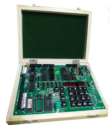
Now let's label that same layout schematically, so the keypad and display map cleanly onto the workflow described below.
Six digits, two for each: leftmost four show the address currently being examined, rightmost two show the data byte stored there. That's the entire window into the machine's 64KB memory space — four hex digits, one address at a time.
The Function Keys, Explained
| Key | What it actually does |
|---|---|
| RESET | Forces the address register to a known starting point (often 0x0000) and blanks pending entry |
| EXAM (Examine) | Loads the typed address into the address register and displays the byte currently stored there |
| EXEC (Execute / Next) | Writes the typed data byte into the currently examined address, then advances to the next address |
| STEP (Single Instruction) | Executes exactly one instruction starting at the current PC, then halts and shows updated register/memory state |
| GO | Sets PC to the typed address and runs continuously, at full CPU speed, until it hits a breakpoint or you hit RESET |
There is no "save," no "undo," and absolutely no forgiveness for a fat-fingered hex digit. If you keyed in 0xE0 where you meant 0xE5, the CPU would happily execute the wrong opcode and you'd spend the next twenty minutes wondering why your loop variable was garbage.
Keying In Our Hand-Assembled Program
Recall the byte listing from the previous lesson. A real 8085 trainer would normally run 8085 opcodes such as MVI, ADD, and JMP; this byte list is reused here only to explain the physical data-entry workflow. The front-panel procedure is the same for any raw byte stream.
| Address | Bytes |
|---|---|
0x2000 |
05 |
0x2001 |
E0 |
0x2002 |
13 |
0x2003 |
E0 |
0x2004 |
01 |
0x2005 |
0F |
0x2006 |
FC |
0x2007 |
CF |
(We're loading it starting at 0x2000 — a typical user-RAM area on an 8085 trainer, well above the monitor ROM.)
Here's the actual sequence of keystrokes, modeled as a workflow — this is muscle memory that thousands of students built over a semester.
Notice that EXEC auto-increments the address. This is the one mercy the hardware grants you — without it, you'd have to re-key the full 4-digit address before every single byte, turning an 8-byte program into 24+ keystrokes instead of roughly 18.
Running It — STEP vs GO
Once the bytes are resident, you have two ways to bring the program to life.
Single-stepping with STEP
STEP was the debugging tool of its era — there was no source-level debugger, no breakpoint UI, no variable watch window. You watched the register display mode (toggled by a separate key on most kits) cycle through A, B, C, D, E, H, L, and flags, one instruction at a time, comparing what you saw against what you'd predicted on paper. If register A didn't show 0x08 after your ADD instruction executed, the bug was somewhere in the eight bytes you'd just keyed in by hand — and you'd re-derive the encoding from the opcode table to find out where you'd transposed a digit.
Full-speed with GO
Pressing GO after setting PC to 0x2000 released the CPU to run at full clock speed — megahertz, not human speed. For a tight loop like ours (ADD then RJMP back to start), the 7-segment address display would blur into a flicker, because the CPU was re-executing those four instructions thousands of times per second. The only visible evidence the program was alive at all was often an LED wired to an output port, blinking at a rate slow enough for a human eye to register — the trainer-kit equivalent of "Hello, World."
Worked Example: Safe Byte Entry Routine
For an 8-byte program starting at 0x2000, use a repeatable checklist instead of trusting your memory:
| Step | Action | Verification |
|---|---|---|
| 1 | Press RESET | Display returns to monitor prompt or known address |
| 2 | Type 2000, press EXAM |
Address field reads 2000 |
| 3 | Type first byte, press EXEC | Address advances to 2001 |
| 4 | Continue one byte per address | Data field matches the byte just entered |
| 5 | Re-examine from 2000 |
Read back every byte before pressing GO |
| 6 | Use STEP first | Confirm PC and registers change as expected |
The read-back pass is not optional. A single wrong nibble can turn a harmless instruction into a jump, store, or restart.
Common Mistakes
| Mistake | What happens | Debugging clue |
|---|---|---|
| Skipping read-back | Program fails far from the typed error | Re-examine memory byte by byte |
| Entering word values instead of bytes | Instruction stream is scrambled | Display always accepts one byte at a time |
| Forgetting EXEC auto-increment | Byte overwrites the previous address | Address field does not advance as expected |
| Running before setting PC | Monitor code or old RAM executes | STEP starts at a surprising address |
| Assuming RAM survives power loss | Program disappears after reset or power cycle | Re-enter or load from nonvolatile storage |
Why the 7-Segment Display Was Enough
It feels almost absurdly minimal by today's standards — six digits, no text, no graphics — but it mapped exactly onto what the CPU itself worked with: an address bus and a data bus, both expressed in hexadecimal because hex maps cleanly onto 4-bit nibbles. There was no abstraction between what you saw and what the silicon was doing. When the display showed address 0x2002, data 0x0F, that was the literal bit pattern sitting on the address and data buses at that instant — the same buses you studied as tri-state lines in lesson 9, now made visible, one hex digit at a time.
Key Takeaway
The trainer kit's hex keypad and 7-segment display weren't a "limited" interface — they were the most honest interface a computer ever offered: you typed the literal bytes that would sit on the data bus, at the literal address that would sit on the address bus, with nothing in between. Every assembler, IDE, and debugger built since exists to spare you exactly this kind of finger-and-memory labor. Having felt it — even just on paper — you're ready to watch that pain get engineered away, one tool at a time.
Further Reading
- Intel, MCS-85 User's Manual, for the 8085 CPU, bus, and instruction background.
- Intel, SDK-85 System Design Kit User's Manual, for the classic trainer-kit workflow.
- Microprocessor trainer kit manuals from Dynalog, VMC, or similar lab boards, for monitor commands and front-panel conventions.