Power in AC Circuits: Real, Reactive, and Apparent Power
DC power is straightforward because voltage and current normally keep the same polarity. AC power needs one extra idea: voltage and current can be out of phase. When they are, some energy does useful work and some energy moves back and forth between the source and reactive components.
Learning Objectives
By the end of this lesson, you should be able to:
- define real power, reactive power, apparent power, and power factor;
- use RMS voltage and current in AC power calculations;
- interpret the power triangle;
- explain why motors and transformers may draw current without converting all of it to useful work;
- size cables, inverters, transformers, and generators using VA where appropriate.
RMS Values and Phase Angle
AC power calculations use RMS voltage and RMS current unless stated otherwise. RMS values represent the DC-equivalent heating effect. If voltage and current are sinusoidal and separated by phase angle theta, then the useful average power depends on cos(theta).
For a resistive heater, voltage and current are in phase, so theta = 0 degrees and cos(theta) = 1. For an inductive motor, current usually lags voltage, so the same RMS volts and amps produce less real power.
The Three AC Power Quantities
| Quantity | Symbol | Unit | Meaning |
|---|---|---|---|
| Real power | P |
watt, W |
energy converted to heat, motion, light, or work |
| Reactive power | Q |
volt-ampere reactive, var |
energy exchanged with inductors and capacitors |
| Apparent power | S |
volt-ampere, VA |
RMS voltage times RMS current, used for equipment loading |
For sinusoidal waveforms:
$$
S = V_\text{RMS} I_\text{RMS}
$$
$$
P = V_\text{RMS} I_\text{RMS}\cos\theta
$$
$$
Q = V_\text{RMS} I_\text{RMS}\sin\theta
$$
$$
S^2 = P^2 + Q^2
$$
Power Triangle
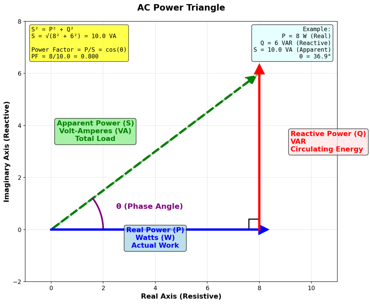
The power triangle is a right triangle when voltage and current are sinusoidal. P is the horizontal side, Q is the vertical side, and S is the hypotenuse. The angle is the phase angle between voltage and current.
A positive Q is commonly used for inductive loads where current lags voltage. A negative Q is commonly used for capacitive loads where current leads voltage. Always check the sign convention used by the meter or standard you are following.
Worked Example
A single-phase motor draws 230 V RMS and 4 A RMS with a power factor of 0.75 lagging.
Apparent power:
$$
S = VI = 230\ V \times 4\ A = 920\ VA
$$
Real power:
$$
P = S \times PF = 920\ VA \times 0.75 = 690\ W
$$
Reactive power:
$$
Q = \sqrt{S^2-P^2}=\sqrt{920^2-690^2}=608\ var
$$
The cable and source must carry current for 920 VA, even though the shaft and losses consume only about 690 W.
Try It: AC Power Calculator
Enter voltage, current, and either phase angle or power factor.
Real-World Impact
Power factor matters because conductors, transformers, switchgear, UPS systems, and inverters are limited by current and heating. A low power factor can force larger equipment even when real power is modest.
Industrial sites often use capacitor banks or active power-factor-correction equipment to reduce reactive current. Do not add correction capacitors blindly: overcorrection, resonance, harmonics, and switching transients can damage equipment. Follow applicable electrical codes and use qualified design review for mains systems.
Common Mistakes
- Using peak voltage instead of RMS voltage in power formulas.
- Sizing a transformer only from watts instead of VA.
- Treating power factor and efficiency as the same thing.
- Assuming all reactive power is bad; some reactive energy is inherent to motors and transformers.
- Ignoring harmonics, where simple sinusoidal formulas may not describe total power accurately.
Summary
Real power does useful work, reactive power oscillates between source and fields, and apparent power describes the RMS loading seen by electrical equipment. Power factor links real power to apparent power. For safe practical design, size equipment from RMS current and VA, then check real power, heat, efficiency, and code requirements.
Further Reading
- IEEE Std 1459: definitions for electric power quantities under sinusoidal and nonsinusoidal conditions.
- IEC 61557-12: power metering and monitoring device performance.
- All About Circuits: AC power and power factor fundamentals.