Phase Angle and Phasor Diagrams: Visualizing AC Relationships
AC analysis becomes clearer when sine waves are represented as rotating vectors called phasors. A phasor captures magnitude and phase at one frequency, turning time-shifted sine waves into geometry.
Learning Objectives
By the end of this lesson, you should be able to:
- define phase angle between AC voltage and current;
- draw basic resistor, inductor, capacitor, and impedance phasors;
- calculate phase angle from resistance and reactance;
- relate phase angle to power factor;
- avoid confusing lead and lag conventions.
What Is a Phasor?
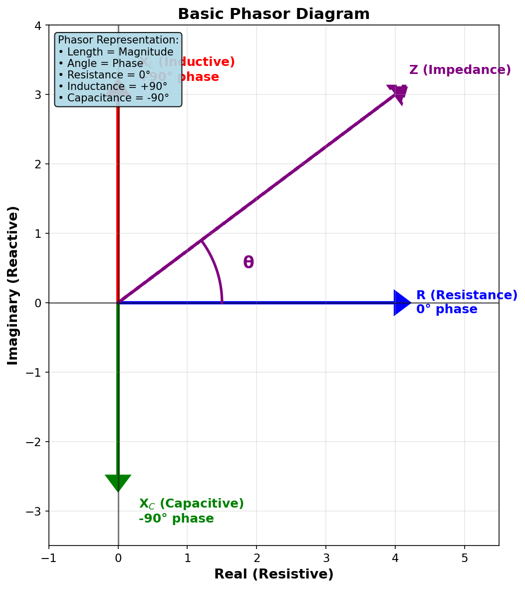
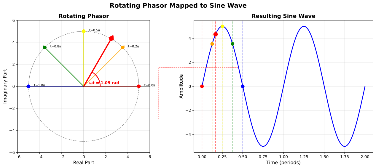
A phasor is a vector representation of a sinusoidal quantity at a fixed frequency. Its length represents magnitude, and its angle represents phase relative to a chosen reference.
A time-domain sine wave can be written as:
$$
v(t)=V_\text{pk}\sin(2\pi ft+\phi)
$$
In a phasor diagram, the phi part becomes the vector angle.
Phase Angle
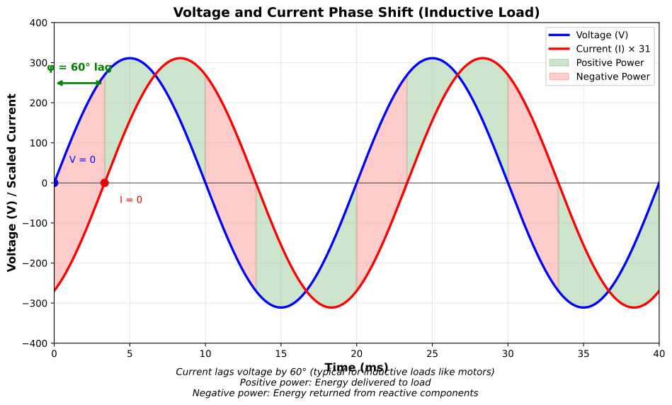
Phase angle is the timing difference between two same-frequency sine waves, expressed as degrees or radians.
$$
360^\circ = 2\pi\ \text{rad}
$$
For voltage and current:
| Circuit | Ideal phase relationship |
|---|---|
| resistor | current in phase with voltage |
| inductor | current lags voltage by 90 deg |
| capacitor | current leads voltage by 90 deg |
title "Lead and lag reference"
time start=0 end=20 unit=ms divisions=5

V: sine label="voltage reference" amplitude=1 cycles=1 unit=norm color=#2563eb
LEAD: sine label="current leads" amplitude=1 cycles=1 phase=45 unit=norm color=#16a34a
LAG: sine label="current lags" amplitude=1 cycles=1 phase=-45 unit=norm color=#dc2626
This waveform is illustrative and normalized.
Building an Impedance Triangle
For a series circuit:
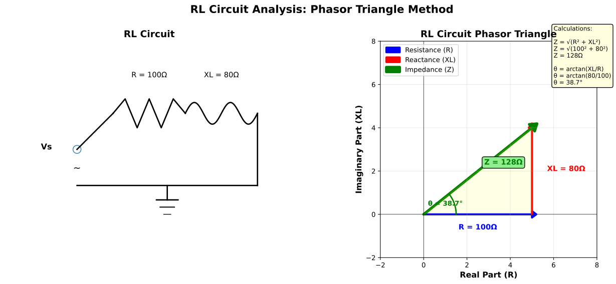
- Draw resistance
Ron the horizontal axis. - Draw inductive reactance
+X_Lupward or capacitive reactance-X_Cdownward. - Draw the impedance
Zas the diagonal vector. - Measure the angle between
RandZ.
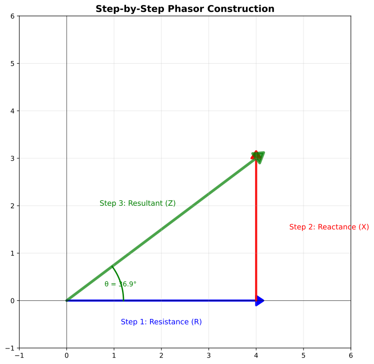
The phase angle is:
$$
\theta=\tan^{-1}\left(\frac{X}{R}\right)
$$
where X is positive for inductive net reactance and negative for capacitive net reactance.
Worked Example: Series RL Circuit
Given R = 100 Ohm and X_L = 80 Ohm:
$$
\theta=\tan^{-1}\left(\frac{80}{100}\right)=38.7^\circ
$$
The circuit is inductive, so current lags the applied voltage by about 38.7 deg.
Try It: Phase Angle Calculator
Enter any two values to calculate the third.
Power Factor
Power factor is the cosine of the phase angle between voltage and current:
$$
\text{PF}=\cos\theta
$$
Real power is:
$$
P=V_\text{RMS}I_\text{RMS}\cos\theta
$$
Reactive power is:
$$
Q=V_\text{RMS}I_\text{RMS}\sin\theta
$$
Apparent power is:
$$
S=V_\text{RMS}I_\text{RMS}
$$
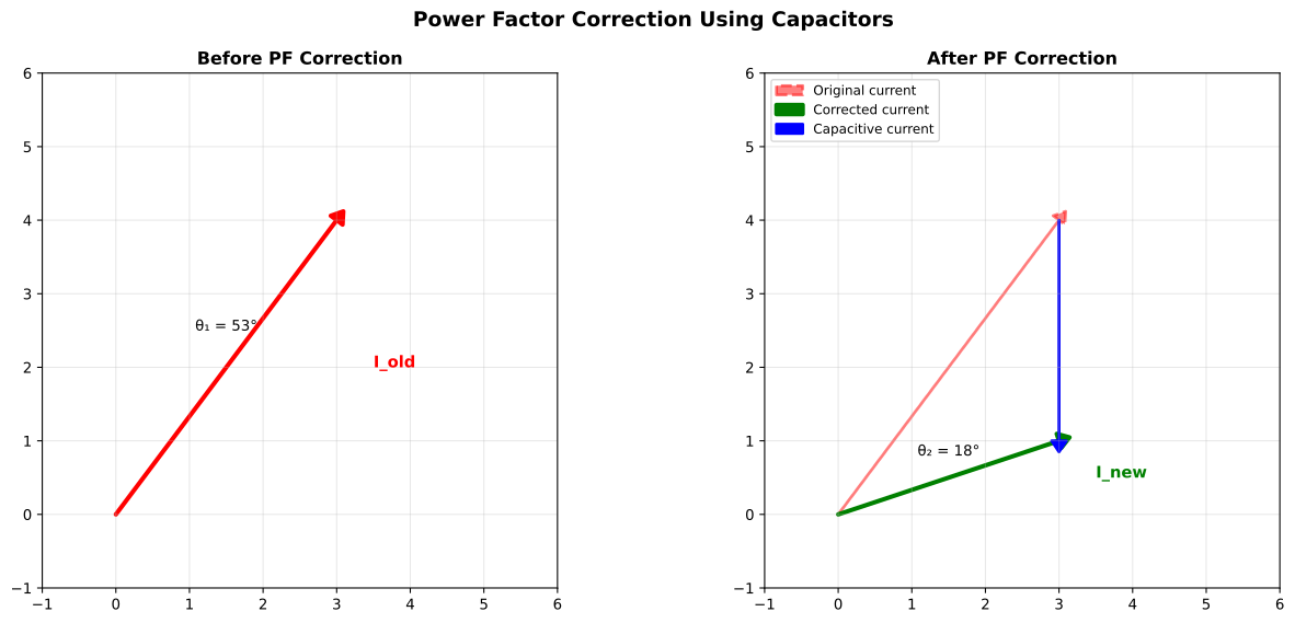
Power systems, motors, transformers, and inverters care about phase angle because current that is out of phase still heats wires and equipment even when it does not perform useful work.
Practical Reading Rules
- Inductive loads, such as motors and transformers, usually draw lagging current.
- Capacitive loads draw leading current.
- A negative calculated
thetausually means net capacitive reactance. - Phasors only combine cleanly for same-frequency sinusoids.
- Distorted waveforms require harmonic analysis, not one simple phasor.
Common Mistakes
- Saying voltage always leads current; the component type decides.
- Forgetting the sign of capacitive reactance.
- Mixing peak and RMS magnitudes on one diagram.
- Drawing phasors for signals of different frequency.
- Treating power factor correction as a simple capacitor add-on without load and safety analysis.
Summary
Phasors turn same-frequency sine waves into vectors. Resistance lies on the real axis, inductive reactance points upward, capacitive reactance points downward, and the impedance vector angle gives phase. The phase angle sets power factor through PF = cos(theta) and is central to AC power, filters, motors, and impedance matching.
Further Reading
- All About Circuits: AC Phase
- All About Circuits: Power in AC Circuits
- Khan Academy: Complex Numbers and Phasors