Impedance: Combining Resistance and Reactance in AC
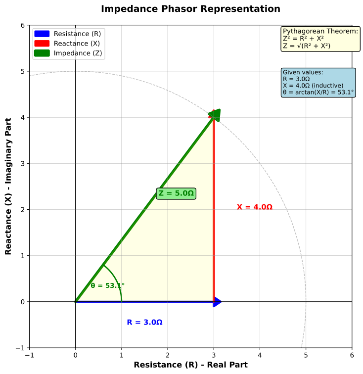
Impedance is the total opposition a circuit presents to AC. It includes resistance, which dissipates energy, and reactance, which stores and returns energy. Because resistance and reactance are phase-shifted, they combine as vectors rather than by ordinary addition.
Learning Objectives
By the end of this lesson, you should be able to:
- represent impedance as
Z = R + jX; - calculate impedance magnitude for series AC circuits;
- distinguish inductive and capacitive reactance signs;
- explain resonance in an RLC circuit;
- use impedance to estimate AC current and loading.
Complex Impedance
The compact AC representation is:
$$
Z=R+jX
$$
where R is resistance in ohms, X is net reactance in ohms, and j represents a 90 deg phase rotation.
For common ideal components:
| Component | Impedance |
|---|---|
| resistor | Z_R = R |
| inductor | Z_L = j2 pi f L |
| capacitor | Z_C = -j/(2 pi f C) |
The sign matters: inductive reactance is positive, capacitive reactance is negative.
Magnitude of Impedance
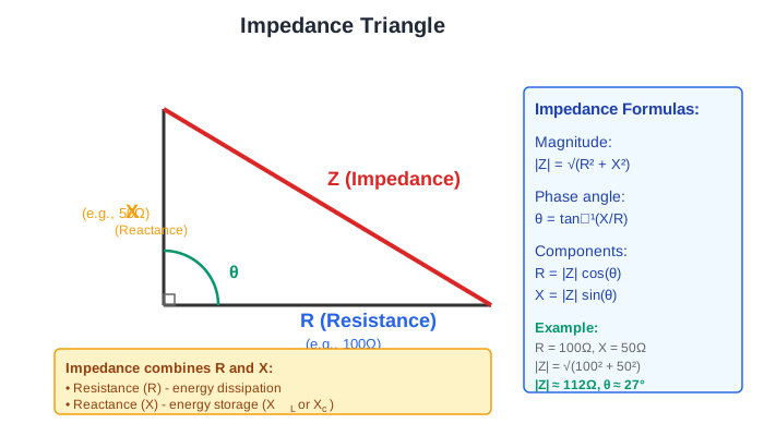
For a series circuit with resistance and net reactance:
$$
|Z|=\sqrt{R^2+X^2}
$$
AC current magnitude follows Ohm's law using RMS values:
$$
I_\text{RMS}=\frac{V_\text{RMS}}{|Z|}
$$
Worked Example: Series RL Circuit
Given R = 100 Ohm and X_L = 80 Ohm:
$$
|Z|=\sqrt{100^2+80^2}=\sqrt{16400}=128\ \Omega
$$
If the applied voltage is 12 V RMS:
$$
I=\frac{12}{128}=93.8\ \text{mA RMS}
$$
Try It: Impedance Calculator
Enter any two values to calculate the third. Use positive reactance for inductive behavior and negative reactance for capacitive behavior.
RC, RL, and RLC Cases
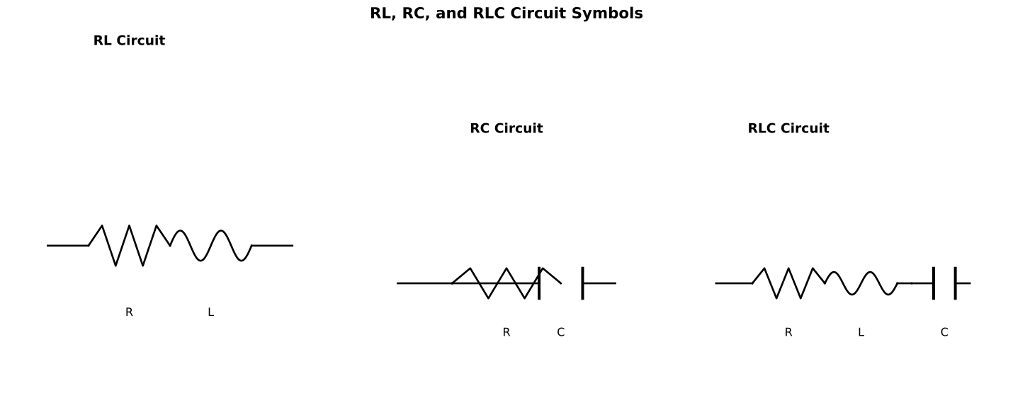
| Circuit | Net reactance | Magnitude |
|---|---|---|
| series RL | X = X_L |
sqrt(R^2 + X_L^2) |
| series RC | X = -X_C |
sqrt(R^2 + X_C^2) |
| series RLC | X = X_L - X_C |
sqrt(R^2 + (X_L - X_C)^2) |
The same component values can look very different at different frequencies because both X_L and X_C depend on frequency.
Resonance
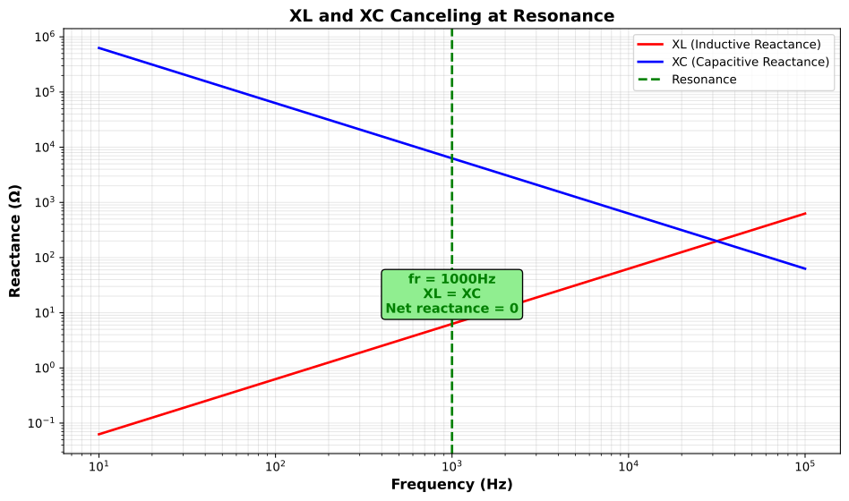
In a series RLC circuit, resonance occurs when inductive and capacitive reactance magnitudes are equal:
$$
X_L=X_C
$$
$$
2\pi f_0 L=\frac{1}{2\pi f_0 C}
$$
Solving for resonant frequency:
$$
f_0=\frac{1}{2\pi\sqrt{LC}}
$$
At resonance, net reactance is zero and the series circuit impedance is approximately R.
Why Impedance Matters
Impedance predicts loading, power transfer, filter behavior, signal attenuation, speaker matching, antenna matching, motor behavior, and measurement error. A meter or oscilloscope probe also has impedance; connecting it changes high-impedance circuits.
Example: a 10x oscilloscope probe may have about 10 MOhm resistance but also input capacitance. At high frequency, that capacitance lowers the effective impedance and can load fast signals.
Common Mistakes
- Adding resistance and reactance as plain numbers.
- Dropping the sign of capacitive reactance too early.
- Using peak voltage in a calculation expecting RMS.
- Assuming speaker impedance is constant with frequency.
- Ignoring source and load impedance when measuring signals.
Summary
Impedance combines resistance and reactance as Z = R + jX. Its magnitude is |Z| = sqrt(R^2 + X^2) for a simple series circuit. Inductive reactance is positive, capacitive reactance is negative, and resonance occurs when X_L = X_C, leaving the circuit approximately resistive.
Further Reading
- All About Circuits: Series R, L, and C
- Keysight: Impedance Measurement Basics
- Analog Devices: Impedance Matching Basics