Reactance of Capacitors and Inductors: AC Opposition
Resistance is opposition that dissipates energy. Reactance is opposition caused by energy storage. Capacitors store energy in an electric field, inductors store energy in a magnetic field, and both create frequency-dependent opposition to AC current.
Learning Objectives
By the end of this lesson, you should be able to:
- calculate capacitive reactance and inductive reactance;
- predict how reactance changes with frequency;
- explain capacitor and inductor phase behavior;
- identify practical uses in coupling, filtering, and power conversion;
- avoid formula and unit mistakes.
DC and AC Behavior
At steady DC, an ideal capacitor behaves like an open circuit after it charges, while an ideal inductor behaves like a short circuit after current settles.
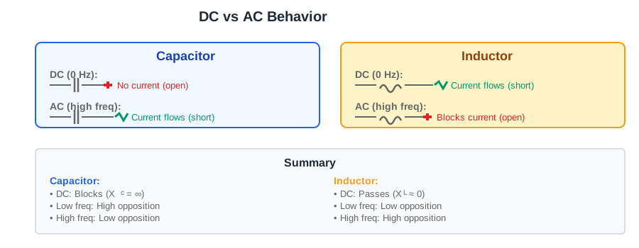
In AC circuits, voltage and current keep changing. The capacitor must charge and discharge, and the inductor must build and collapse magnetic field energy. That is why frequency matters.
Capacitive Reactance
Capacitive reactance is:
$$
X_C=\frac{1}{2\pi f C}
$$
where X_C is in ohms, f is in hertz, and C is in farads.
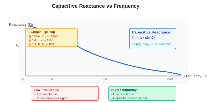
As frequency increases, X_C decreases. A capacitor blocks DC, opposes low frequency strongly, and passes high frequency more easily.
Worked example for C = 1 uF:
| Frequency | Calculation | X_C |
|---|---|---|
100 Hz |
1/(2 pi 100 1e-6) |
1592 Ohm |
1 kHz |
1/(2 pi 1000 1e-6) |
159 Ohm |
10 kHz |
1/(2 pi 10000 1e-6) |
15.9 Ohm |
Inductive Reactance
Inductive reactance is:
$$
X_L=2\pi f L
$$
where X_L is in ohms, f is in hertz, and L is in henries.
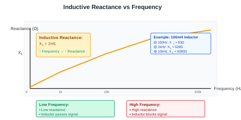
As frequency increases, X_L increases. An inductor passes DC easily in the ideal case and opposes high-frequency current changes.
Worked example for L = 100 mH:
| Frequency | Calculation | X_L |
|---|---|---|
100 Hz |
2 pi 100 0.1 |
62.8 Ohm |
1 kHz |
2 pi 1000 0.1 |
628 Ohm |
10 kHz |
2 pi 10000 0.1 |
6283 Ohm |
Phase Relationship
Reactance also changes the timing between voltage and current.
| Component | Phase rule |
|---|---|
| resistor | voltage and current are in phase |
| capacitor | current leads voltage by 90 deg in the ideal case |
| inductor | current lags voltage by 90 deg in the ideal case |
title "Ideal reactive phase examples"
time start=0 end=20 unit=ms divisions=5

V: sine label="voltage reference" amplitude=1 cycles=1 unit=norm color=#2563eb
IC: sine label="capacitor current leads" amplitude=1 cycles=1 phase=90 unit=norm color=#16a34a
IL: sine label="inductor current lags" amplitude=1 cycles=1 phase=-90 unit=norm color=#dc2626
This waveform is illustrative and normalized.
Reactance Calculator
Select the component type, enter frequency and component value to calculate reactance. Or enter frequency and reactance to find the required component value.
Applications
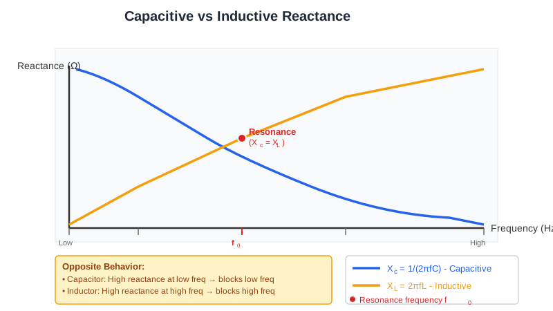
Capacitors are used for AC coupling, bypassing, low-pass filters, high-pass filters, timing networks, and switched-mode converter energy transfer. Inductors are used for current smoothing, EMI filters, transformers, tuned circuits, and energy storage in converters.
| Function | Reactive behavior used |
|---|---|
| decoupling capacitor | low impedance at high frequency |
| AC coupling capacitor | blocks DC, passes signal band |
| inductor input filter | resists fast current change |
| LC tank | energy trades between electric and magnetic fields |
| crossover network | frequency-dependent current division |
Real Components
Real capacitors have equivalent series resistance, equivalent series inductance, leakage, voltage coefficient, tolerance, and dielectric limits. Real inductors have winding resistance, saturation current, core loss, self-resonance, and stray capacitance. At high frequency, parasitics can dominate the ideal formula.
Common Mistakes
- Using microfarads or millihenries directly without converting units.
- Writing the inductor formula incorrectly; it is
X_L = 2 pi f L. - Forgetting that reactance is frequency-dependent.
- Assuming ideal
90 degphase for lossy real components. - Ignoring capacitor voltage rating or inductor saturation current.
Summary
Capacitive reactance decreases with frequency: X_C = 1/(2 pi f C). Inductive reactance increases with frequency: X_L = 2 pi f L. These two relationships explain AC coupling, filters, resonance, EMI suppression, and many power-conversion behaviors.
Further Reading
- All About Circuits: Reactance and Impedance
- Electronics Tutorials: Capacitive Reactance
- Electronics Tutorials: Inductive Reactance