Real Resistors: Tolerance, Power Rating, and Selection
An ideal resistor has exactly one resistance value forever. A real resistor has tolerance, power dissipation, temperature drift, voltage limits, parasitic inductance and capacitance, noise, and a package that affects assembly and heat flow. Good circuit design treats the resistor as a component with limits, not just a number in ohms.
Learning Objectives
By the end of this lesson, you should be able to:
- calculate tolerance limits for a resistor value;
- estimate resistor power and select a safe rating;
- explain temperature coefficient in ppm per degree Celsius;
- choose between common resistor technologies and packages;
- avoid common reliability failures in resistor selection.
Tolerance
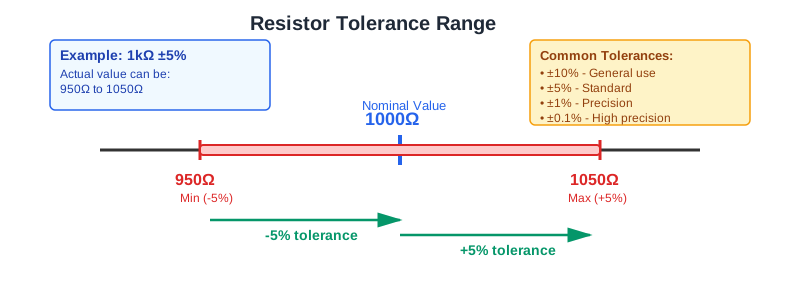
Tolerance is the allowed difference between nominal value and actual value when the component is supplied.
For a 1 kOhm resistor with 5% tolerance:
$$
R_\text{min}=1000(1-0.05)=950\ \Omega
$$
$$
R_\text{max}=1000(1+0.05)=1050\ \Omega
$$
Common tolerance choices:
| Use case | Typical tolerance |
|---|---|
| LED current limiting, pullups, general logic | 5% or 1% |
| filters, dividers, timing networks | 1% or better |
| gain-setting and measurement | 0.1% to 0.01% |
| matched ratios | resistor network or specified ratio tolerance |
Tolerance affects worst-case design. In a divider, both resistors can move in opposite directions, so output error can be larger than either single tolerance suggests.
Standard Value Series
Resistors are sold in preferred value series. The E12 series has 12 values per decade and is commonly associated with 10% or 5% work. E24, E96, and E192 provide finer spacing for precision designs.
E12 values in one decade:
10, 12, 15, 18, 22, 27, 33, 39, 47, 56, 68, 82
Multiply by powers of ten to get values such as 1.0 kOhm, 4.7 kOhm, or 82 kOhm.
Power Rating
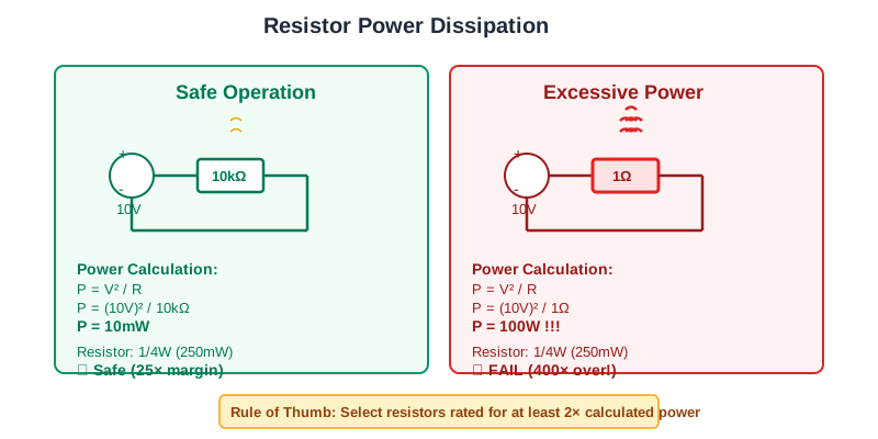
A resistor converts electrical energy into heat. Use the form of the power equation that matches what you know:
$$
P=VI
$$
$$
P=I^2R
$$
$$
P=\frac{V^2}{R}
$$
Worked examples:
| Situation | Power | Selection note |
|---|---|---|
10 kOhm across 10 V |
10 mW |
0.125 W is usually fine |
1 kOhm with 10 mA |
100 mW |
0.25 W gives margin |
1 Ohm across 10 V |
100 W |
needs a power resistor and heat design |
Use margin. A practical starting rule is to keep steady dissipation below 50% of the resistor rating unless the datasheet, enclosure temperature, PCB copper, and airflow justify otherwise.
Temperature Coefficient
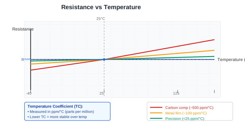
Temperature coefficient tells how resistance changes with temperature, usually in parts per million per degree Celsius.
$$
\Delta R=R_0 \times \text{TCR} \times 10^{-6} \times \Delta T
$$
A 10 kOhm resistor with 100 ppm/degC TCR over a 50 degC rise changes by:
$$
\Delta R=10000\times100\times10^{-6}\times50=50\ \Omega
$$
That is 0.5%, even before aging and initial tolerance.
Technology and Package
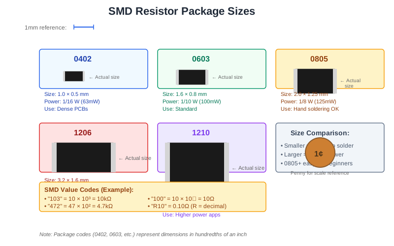
Through-hole resistors are easy to prototype and can handle higher power in larger bodies. Surface-mount resistors are compact and assembly-friendly but their power rating depends strongly on PCB copper area and ambient temperature.
| Type | Strength | Watch out |
|---|---|---|
| carbon film | low cost | wider tolerance, more noise |
| metal film | stable, low noise | limited pulse energy |
| thick-film SMD | cheap and common | voltage coefficient, noise |
| thin-film SMD | precision and ratio stability | cost, pulse limits |
| wirewound | high power, low drift | inductance at high frequency |
| current sense | low resistance, Kelvin options | self-heating and thermal EMF |
Voltage, Pulse, and Layout Limits
High resistance does not automatically mean safe at high voltage. Check maximum working voltage and overload voltage. For high-energy pulses, check surge curves rather than average power alone.
Practical layout checks:
- keep hot resistors away from electrolytic capacitors and temperature sensors;
- use enough copper for heat spreading;
- use series resistors when voltage rating is the limiting factor;
- keep high-impedance nodes clean and guarded where leakage matters;
- use Kelvin connections for milliohm current shunts.
Selection Checklist
- Choose nominal value from the required circuit function.
- Calculate worst-case tolerance impact.
- Calculate steady power and pulse energy.
- Apply derating for ambient temperature and enclosure heat.
- Check voltage rating, TCR, noise, and technology.
- Choose package size for assembly, heat, and availability.
- Confirm lifecycle status and second sources.
Common Mistakes
- Selecting only by resistance value and ignoring power.
- Running a resistor continuously at its full rated wattage.
- Using a wirewound resistor where inductance affects fast signals.
- Ignoring divider tolerance in ADC and reference circuits.
- Forgetting maximum voltage on high-value resistors.
Summary
A resistor selection is reliable only when value, tolerance, power, temperature coefficient, voltage rating, pulse rating, package, and technology all fit the circuit. Calculate worst-case resistance and heat, then choose a standard available part with enough margin for the real operating environment.
Further Reading
- Vishay: Resistors 101
- Yageo: Chip Resistor Technical Guide
- Analog Devices: Precision Resistor Considerations